Patient telemetry device with auto-compensation for impedance changes in leadset antenna

a patient telemetry and leadset technology, applied in the field of remote patient monitoring telemetry systems, can solve the problems of inconvenient patient treatment, lack of durability, and stiffness of coaxial ecg lead wires, and achieve the effects of low capacitance tvs, low cost, and effective beam steering

Inactive Publication Date: 2005-06-14
GE MEDICAL SYST INFORMATION TECH
View PDF24 Cites 14 Cited by
  • Summary
  • Abstract
  • Description
  • Claims
  • Application Information

AI Technical Summary

Benefits of technology

[0014]Another feature of the invention involves using the multiple antenna conductors of the coaxial or non-coaxial leads as elements of a phased antenna array. In one embodiment of a transceiver system, each such antenna conductor is coupled to a respective phase shifter capable of adjusting the phases of signals received and radiated by that antenna conductor. During receive events, a phase detection circuit monitors the phases of the respective RF signals received by the antenna conductors, and controls the phase shifters to compensate for phase differences. During transmission events, the phase shifters are used to effectively steer the beam formed by the antenna array in the direction of a receiving station and / or to reject an interference source. The antenna beam may also be steered passively (without transmitting) to locate a base station.
[0015]Another inventive feature, which similarly may be used alone or in combination with the aforementioned features, is an improved circuit for protecting the remote transceiver's circuitry, or the circuitry of another type of device that receives signals from an ECG lead set, from damage caused by defibrillation pulses. In a preferred embodiment, the circuit includes a low capacitance, transient voltage suppression (TVS) circuit connected between the ECG signal path and ground, and further includes a current-limiting resistor connected in-line along the signal path. Separate protection circuits of this type may be provided along each ECG signal path. The use of low capacitance TVS circuits allows small, low cost, surface-mount current limiting resistors to be used in place of the relatively large current-limiting resistors used in conventional designs.

Problems solved by technology

One problem with existing designs is that the coaxial ECG lead wires tend to be relatively stiff in comparison to other types of wires.
As a result, the leads cause discomfort to patients and tend to lack durability.
Another problem with existing designs, and particularly with ambulatory transmitter and transceiver designs, is that data transmissions are highly susceptible to attenuation caused by the patient's body or nearby objects.
This problem is frequently experienced when the patient is in bed.
Further, the patient's position in bed may cause a portion of the antenna to be positioned close to a bed rail or other grounded metal object, causing the entire antenna to de-tune.
In these situations, the patient's real time physiologic data typically can not be remotely monitored with sufficient reliability.
Yet another problem with existing telemetry devices, and other types of devices that receive signals from an ECG lead set, is that they do not provide an adequate solution to the problem of protecting against defibrillation pulses.
These resistors tend to be large, high-power components, and tend to increase the manufacturing cost of the device while providing only limited protection.
Thus, for example, when one antenna produces data errors as the result of a lead touching a bed rail, the control circuit may switch to an antenna that does not use the affected lead.

Method used


Image

  • Patient telemetry device with auto-compensation for impedance changes in leadset antenna
  • Patient telemetry device with auto-compensation for impedance changes in leadset antenna
  • Patient telemetry device with auto-compensation for impedance changes in leadset antenna

Examples


Embodiment Construction

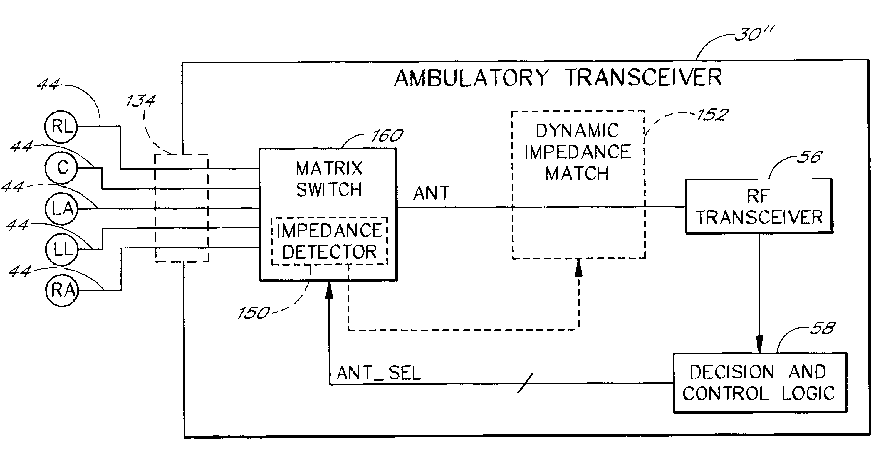
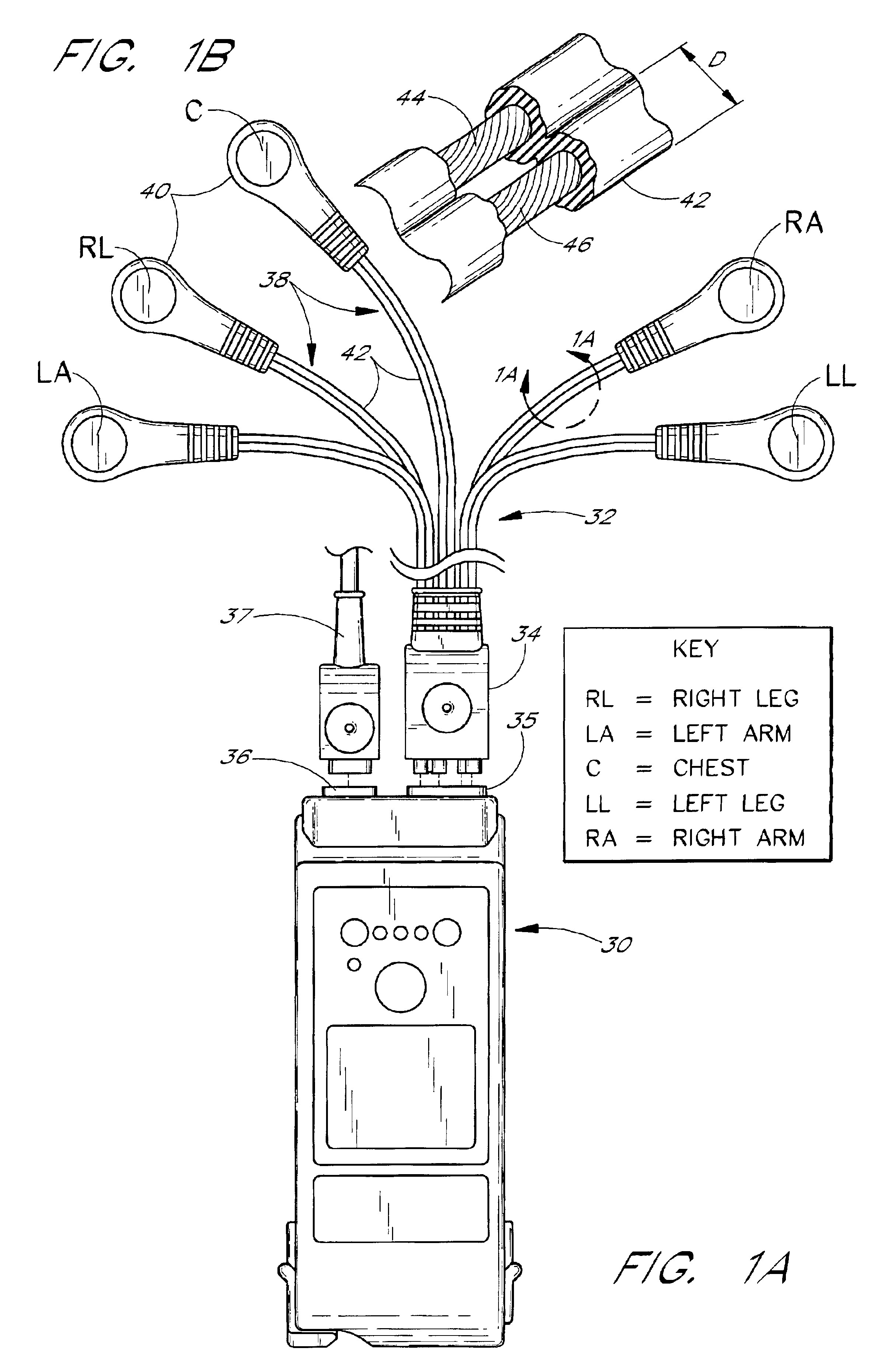
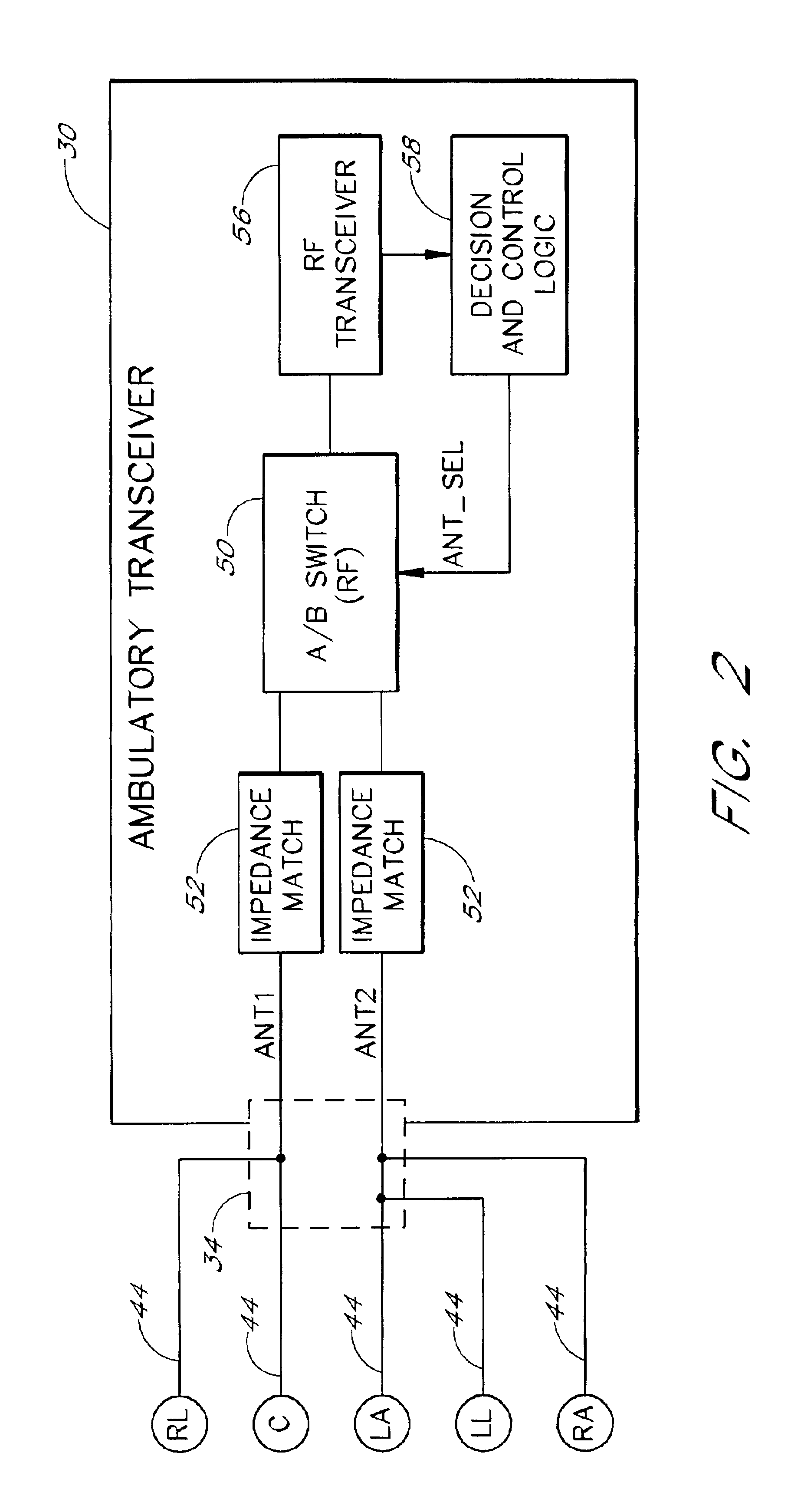
[0029]An ambulatory transceiver system that embodies some of the inventive features mentioned above will now be described with reference to FIGS. 1-6. Additional designs incorporating other inventive features will then be described with reference to FIGS. 7-9. As will be apparent, many of the disclosed features can be used or practiced independently of others, and without many of the implementation-specific details set forth herein. In addition, many of the inventive features that are described separately can be appropriately combined within an ambulatory or other telemetry device.

[0030]Although the specific embodiments illustrated in the drawings involve a transceiver unit that attaches to an ECG lead set, many of the disclosed features may be embodied within or used with other types of devices. Examples of other devices include patient telemetry devices that are merely RF transmitters and not RF receivers (referred to herein as “unidirectional transmitters”), and devices that sens...


PUM


Abstract

Various designs and features of an ambulatory transceiver and ECG lead set are disclosed for use in remote patient monitoring. One feature involves the use of unshielded, dual-conductor lead wires in which one conductor carries the patient's ECG signal and the other conductor provides an RF antenna element for the transceiver. The lead wires used in one embodiment provide improved flexibility, durability, and antenna performance over conventional lead sets with shielded wires. Another feature involves an antenna diversity scheme in which the transceiver switches between two or more ECG-lead antennas, each of which is formed from one or more ECG leads of the lead set. Another feature involves the use of a circuit within the transceiver to monitor, and dynamically compensate for changes in, the impedance of an ECG-lead antenna or a conductor thereof. Another feature is an improved circuit for protecting the transceiver from damage caused by defibrillation pulses.

Description

RELATED APPLICATION[0001]This application claims the benefit of U.S. Provisional Appl. No. 60 / 273,136, filed Mar. 2, 2001, titled REMOTE TRANSCEIVER AND LEAD SET DESIGNS FOR MEDICAL TELEMETRY.FIELD OF THE INVENTION[0002]The present invention relates to telemetry systems for remote patient monitoring. More specifically, the invention relates to the use of leads, such as ECG (electrocardiograph) leads, to provide antennas for ambulatory or other remote telemetry devices.BACKGROUND OF THE INVENTION[0003]A variety of patient monitoring systems exist that allow the physiologic data of patients within a medical facility to be monitored remotely using wireless communications. These systems commonly include remote transmitters or transceivers that collect, and transmit over a wireless channel, the physiologic data of respective patients. This physiologic data may include, for example, real-time electrocardiograph (ECG) waveforms, SpO2 levels, and non-invasive blood pressure readings. The tr...

Claims


Application Information

Patent Timeline
Patent Type & Authority Patents(United States)
IPC IPC(8): A61B5/0402A61B5/00A61B5/0428A61B5/04A61B5/308
CPCA61B5/0006A61B5/04286A61B5/04004Y10S128/903A61B2562/222A61B5/30A61B5/303
Inventor CARTER, SCOTT J.FLANDERS, EDWARD L.KATO, ROBERT B.
Owner GE MEDICAL SYST INFORMATION TECH
Why Eureka
Try Eureka