

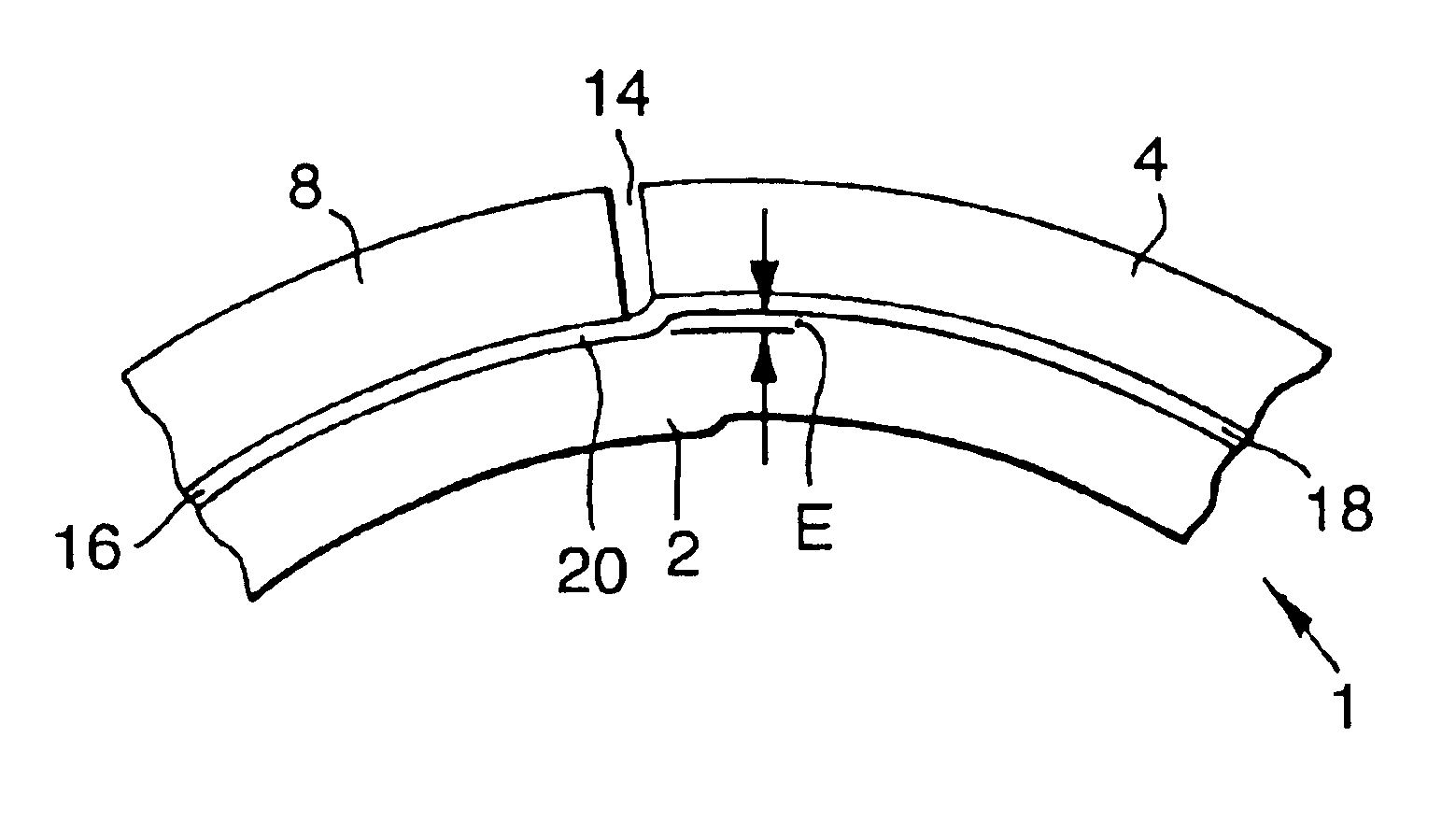
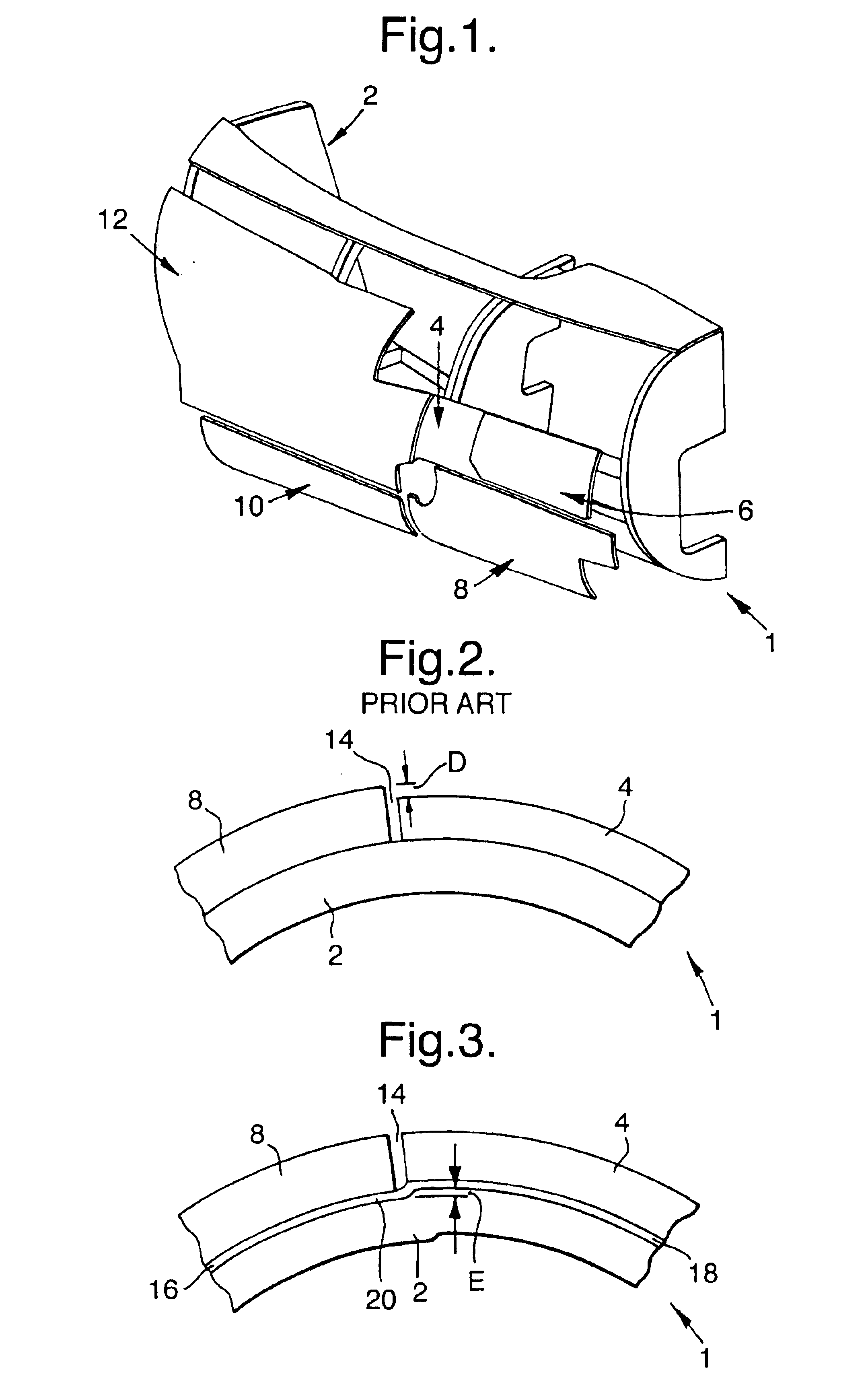
Manufacturing and assembly of structures using shims
a technology of manufacturing and assembly, which is applied in the direction of manufacturing tools, transportation and packaging, measurement/indication equipment, etc., can solve the problems of increasing drag or turbulence, and reducing the service life of the structur
- Summary
- Abstract
- Description
- Claims
- Application Information
AI Technical Summary
Benefits of technology
Problems solved by technology
Method used
Image

Examples
example 2
[0054]Pre-heat the Bisphenol A epoxy resin to a temperature at which the viscosity is sufficiently lowered for filler to be incorporated. This temperature will be dependent upon the nature of the epoxy resin and the power rating of the mixing equipment, and will be typically approximately 120-160° C.
[0055]Add in the talc filler, heat in a vacuum to degas the mixture and stir.
[0056]Add in the glass spheres, degas the mixture and stir.
[0057]Add in the air release agent, the adhesion improving agent and the aluminium powder and degas the mixture.
[0058]Add in the fumed silica.
[0059]Cool the mixture to below 60° C. (preferably to 48° C.) and degas.
[0060]Add the curing agent.
[0061]Discharge the mixture, a rollable dough-like substance, on to film forming equipment such as a reverse roll coater, knife over roller coater, extruder or conveyor press.
[0062]Form film of desired thickness, incorporating a supporting scrim material if required, and keep the shim material at refrigerated temperat...
PUM
| Property | Measurement | Unit |
|---|---|---|
| thickness | aaaaa | aaaaa |
| temperatures | aaaaa | aaaaa |
| temperature | aaaaa | aaaaa |
Abstract
Description
Claims
Application Information