Gas compressor control device and gas turbine plant control mechanism

a gas compressor and control device technology, applied in mechanical equipment, machines/engines, liquid fuel engines, etc., can solve problems such as fuel oscillation, combustor breakage, and the conventional method of securing long piping between the gas turbine and the gas compressor is nearing its limits

Active Publication Date: 2005-06-21
MITSUBISHI HITACHIPOWER SYST LTD
View PDF5 Cites 30 Cited by
  • Summary
  • Abstract
  • Description
  • Claims
  • Application Information

AI Technical Summary

Benefits of technology

[0019]The present invention has been accomplished in the light of the earlier technologies. Its object is to provide a gas compressor control device and a gas turbine plant control mechanism which are capable of preventing an excessive increase in a fuel gas pressure within fuel gas piping during occurrence of a sudden load fall (load rejection or load loss), even when the fuel gas piping connecting a gas turbine and a gas compressor together is short.
[0027]Because of the above-described features, in the event of load loss or load rejection, the recycle valve can be opened in a preceding manner, and the inlet guide vane (IGV) can be closed in a preceding manner. As a result, the fuel gas pressure at the gas compressor outlet can be lowered to suppress the elevation of the fuel gas pressure at the gas turbine inlet. Thus, stable operation can be performed.
[0038]Because of the above-described cooperative control by the gas turbine control device and the gas compressor control device, in the event of load loss or load rejection, the recycle valve can be opened in a preceding manner, and the inlet guide vane (IGV) can be closed in a preceding manner. As a result, the fuel gas pressure at the gas compressor outlet can be lowered to suppress the elevation of the fuel gas pressure at the gas turbine inlet. Thus, stable operation can be performed.

Problems solved by technology

As a result, differential pressure control of the gas turbine may fail to accommodate such pressure changes, so that an excessive amount of fuel is charged into the gas turbine 2, causing breakage to the combustor or fuel oscillations.
With this restricted premises area, the conventional method of securing long piping between the gas turbine and the gas compressor is nearing its limits.

Method used


Image

  • Gas compressor control device and gas turbine plant control mechanism
  • Gas compressor control device and gas turbine plant control mechanism
  • Gas compressor control device and gas turbine plant control mechanism

Examples


example

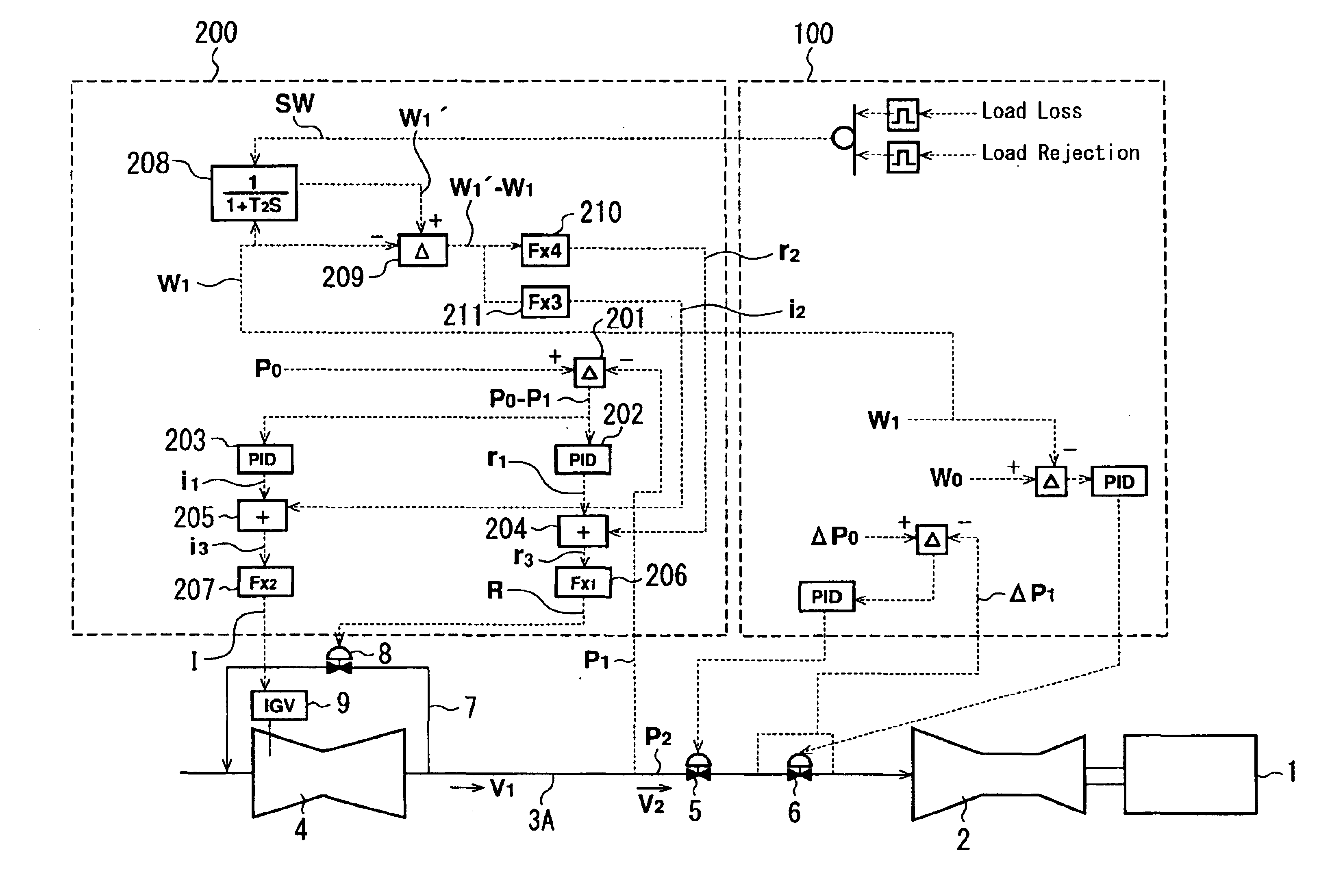
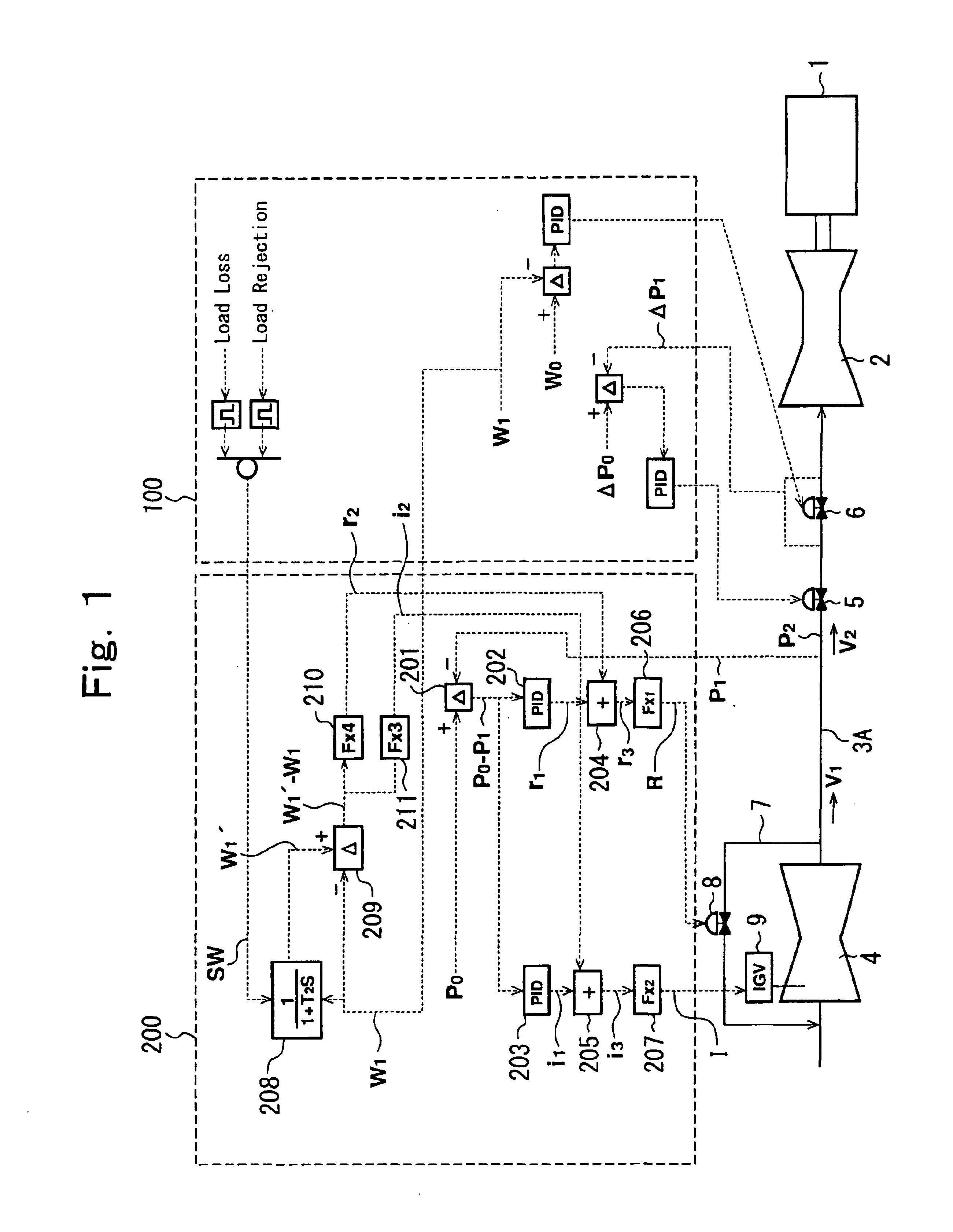
[0065]Next, an example for embodying the present invention will be described with reference to FIG. 1. Portions exhibiting the same capabilities as in the earlier technology shown in FIG. 4 are assigned the same numerals, and descriptions of these portions will be offered briefly.

[0066]As shown in FIG. 1, a gas compressor 4 is provided with a recycle pipe 7, a recycle valve 8, and an IGV (inlet guide vane) 9. A pressure control valve 5 and a flow control valve 6 are interposed in fuel gas piping 3A. A fuel gas, increased in pressure by the gas compressor 4, is passed through the fuel gas piping 3A and supplied to a gas turbine 2. The gas turbine 2 supplied with the fuel gas rotationally drives a generator 1 to generate electric power.

[0067]The fuel gas piping 3A is shorter than the conventional fuel gas piping 3. Except that the fuel gas piping 3A is shorter, the above-mentioned mechanical layout and configuration are the same as in the earlier technology (see FIG. 4).

[0068]A gas tu...


PUM


Abstract

A gas compressor control device and a gas turbine plant control mechanism are disclosed. A fuel gas pressurized by a gas compressor is supplied to a gas turbine via fuel gas piping. A gas turbine control device adjusts the flow rate of the fuel gas into the gas turbine by exercising opening and closing control of a pressure control valve and a flow control valve. The gas compressor control device controls a fuel gas pressure at the outlet of the gas compressor by effecting opening and closing control of a recycle valve and an IGV. If load rejection or load loss occurs, the gas compressor control device opens the recycle valve in a preceding manner and closes the IGV in a preceding manner. Thus, elevation of the fuel gas pressure at the gas compressor outlet can be prevented, and elevation of a fuel gas pressure at an inlet of the gas turbine can be suppressed, thereby ensuring stable operation.

Description

[0001]The entire disclosure of Japanese Patent Application No. 2002-265138 filed on Sep. 11, 2002, including specification, claims, drawings and summary, is incorporated herein by reference in its entirety.BACKGROUND OF THE INVENTION[0002]1. Field of the Invention[0003]This invention relates to a gas compressor control device and a gas turbine plant control mechanism, which are designed to be capable of suppressing a rise in the pressure of a fuel gas supplied to a gas turbine, even if load rejection or load loss occurs.[0004]2. Description of the Related Art[0005]In a gas turbine plant, as shown in FIG. 4, a gas turbine 2 for rotationally driving a generator 1 is supplied with a fuel gas from a gas compressor 4 via fuel gas piping 3. That is, the fuel gas for use in the gas turbine 2 is pressurized by the gas compressor 4 to a pressure suitable for the gas turbine 2.[0006]The amount of fuel consumed by the gas turbine 2 varies with a generator load required of the gas turbine 2. In...

Claims


Application Information

Patent Timeline
Patent Type & Authority Patents(United States)
IPC IPC(8): F02C9/28F02C9/00F02C9/20F02C9/30F04D29/56
CPCF02C9/20F02C9/28F05D2270/091F05D2270/3013F05D2270/3011
Inventor TANAKA, SATOSHI
Owner MITSUBISHI HITACHIPOWER SYST LTD
Why Eureka
Try Eureka