Shock absorber

Inactive Publication Date: 2005-06-21
ASTEER
View PDF8 Cites 34 Cited by
  • Summary
  • Abstract
  • Description
  • Claims
  • Application Information

AI Technical Summary

Benefits of technology

[0014]Therefore, the load transmission member may be formed by at least a pair of curved cover members having a side member-side mounting edge extending along a shape of the outer periphery of the mounting part, and a tube-side mounting edge extending along a shape of the outer side surface of the larger-diameter tube portion continuously through the intersectional part determined by connecting the mounting part and the larger-diameter tube portion from the side member-side mounting edge. Owing to this structure, the opened side portions of the load transmission member are closed, and the structural strength of the load transmission member with respect to the buckling can be heightened, so that the possibility of occurrence of the collapse or deformation of the front end portion of the side member can be further reduced at once.
[0015]According to the present invention, the ef

Problems solved by technology

However, when a local load is imparted to the intersection of the two-stage tube 1 and side member 8 which supports the two-stage tube 1 thereon, as mentioned above, the vehicle body member becomes liable to be relatively deformed due to the concentrated impact energy, so that it becomes unable to make the best use of the performance which the shock absorber posse

Method used


Image

  • Shock absorber
  • Shock absorber
  • Shock absorber

Examples


Example

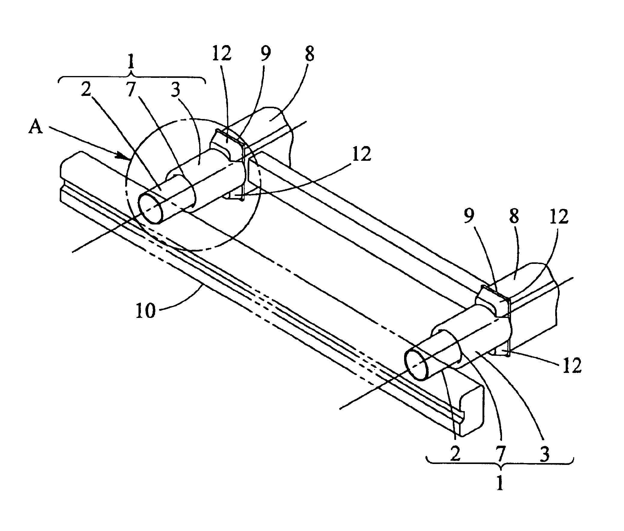
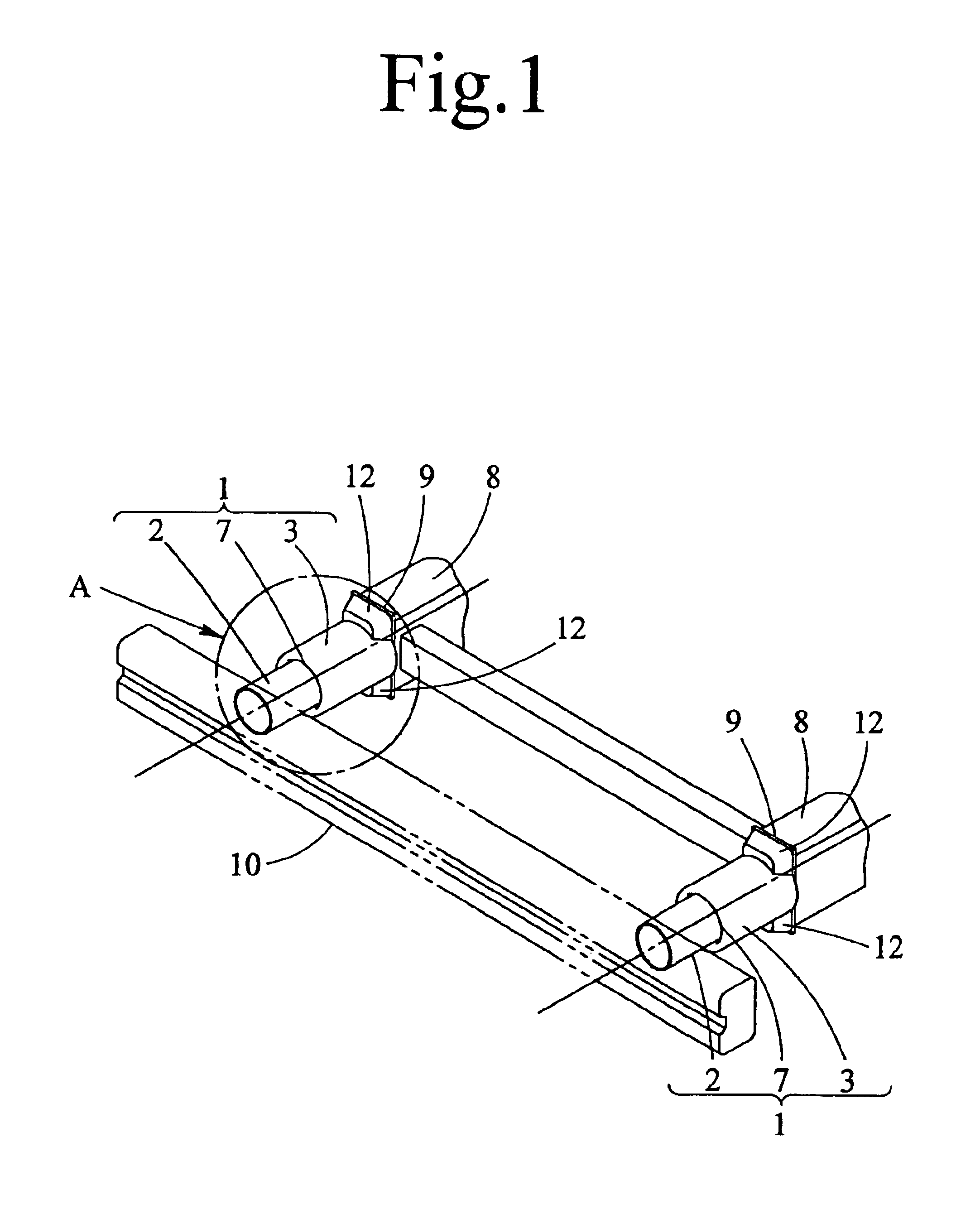
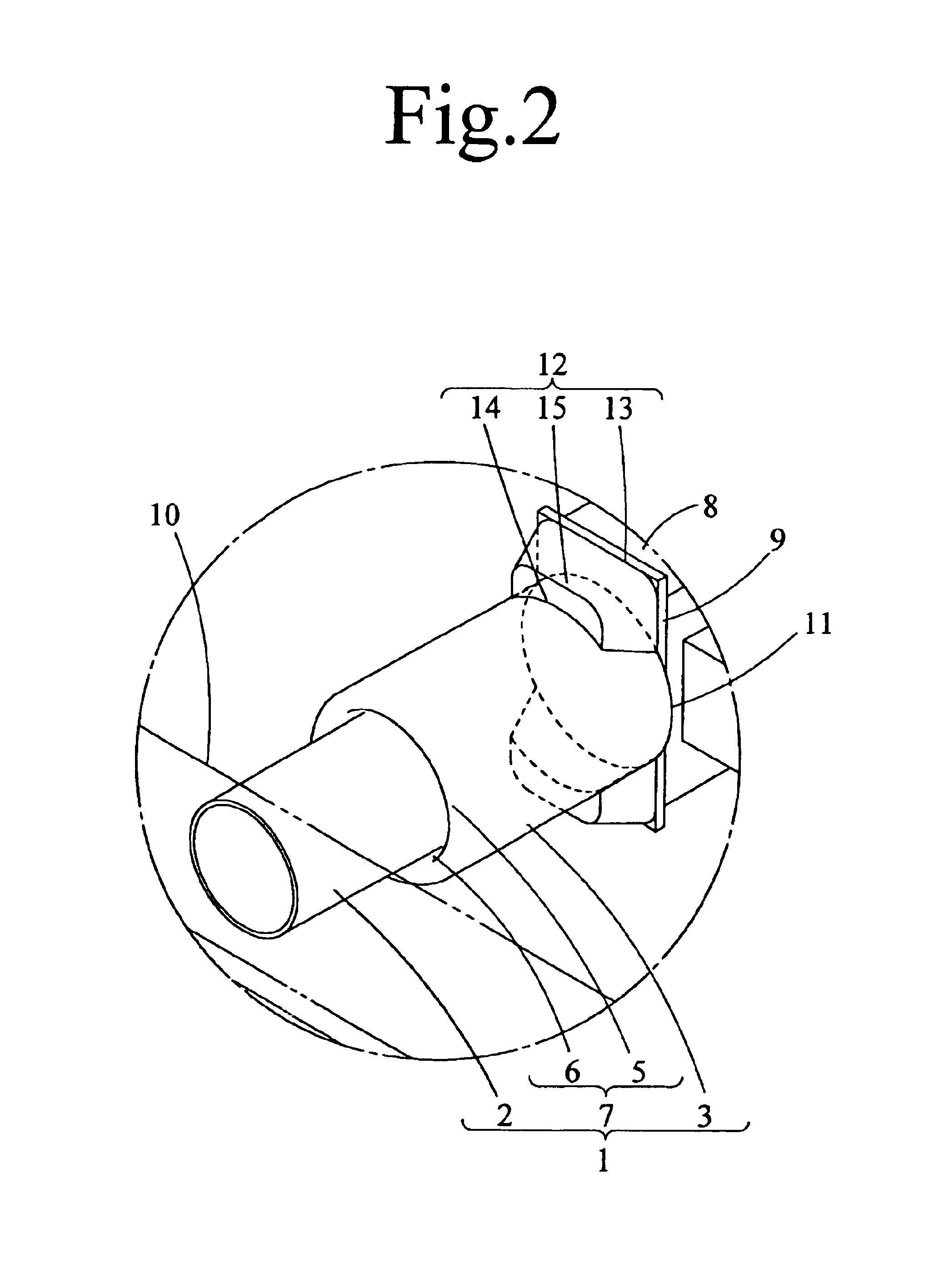
[0027]As shown in FIG. 1, FIG. 2 and FIG. 4 to FIG. 6, the shock absorber in this example uses a two-stage tube 1 formed by a stepped portion 7 at which a smaller-diameter tube portion 2 and a larger-diameter tube portion 3 are joined integrally by partially reducing or partially enlarging a straight tube that can be plastically deformed. The stepped portion 7 of the two-stage tube 1 is formed by axially absorbing the smaller-diameter tube portion 2 in inside of the larger-diameter tube portion 3 (refer to a one-dot chain line in FIG. 1, and the same applies to the similar description to be given later). The stepped portion 7 has a substantially S-shaped cross sectional shape formed by integrally joining the rear end peripheral edge 4 of the smaller-diameter tube portion 2 having arcuate shape cross-sectionally and the cross-sectionally arcuate front end peripheral edge 5 of the larger-diameter tube portion 3 having arcuate shape cross-sectionally with each other via a tubular wall ...


PUM


Abstract

A shock absorber capable of preventing the collapse or deformation of a vehicle body member when a local load applied to a bumper, without being influenced by the arrangement and construction of the vehicle body member. The shock absorber comprises a multi-diameter stepped tube having different diameter tube portions integrally formed by partially reducing or partially enlarging a straight tube that can be plastically deformed through a stepped portion connecting those tube portions under installation of which a smaller-diameter tube portion connecting to the bumper and of which a larger-diameter tube portion connecting to the side member, a mounting part having a quadrilateral shape with a diagonal length of which is longer than the diameter of the larger-diameter tube portion and positioned at a front end of the side member, and load transmission members fixed between an outer side surface of the larger-diameter tube portion and the mounting part.

Description

BACKGROUND OF THE INVENTION[0001]1. Field of the Invention[0002]This invention relates to a shock absorber adapted to absorb impact energy therein, such as a load imparted to a bumper of an automobile, for example, when the automobile collides with something, and prevent or suppress the transmission of the impact energy to a vehicle body member. More particularly, the invention relates to a shock absorber adapted to absorb impact energy therein by converting the impact energy into deformation energy for plastically deforming a tube portion thereof.[0003]2. Description of the Related Art[0004]In order to prevent or suppress the transmission of impact energy, a load imparted to a bumper of an automobile to a vehicle body member, a shock absorber adapted to absorb the impact energy therein is usually provided between the bumper and a side member. Such shock absorbers include a cylinder type shock absorber, and a plastic deformation type shock absorber. Although the latter plastic defor...

Claims


Application Information

Patent Timeline
IPC IPC(8): B60R19/24B60R19/34B60R19/18
CPCB60R19/34
Inventor SHIMOTSU, KOJI
Owner ASTEER
Why Eureka
Try Eureka