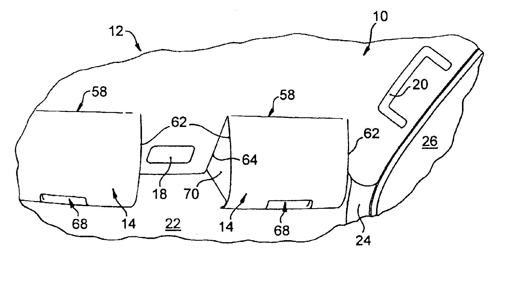
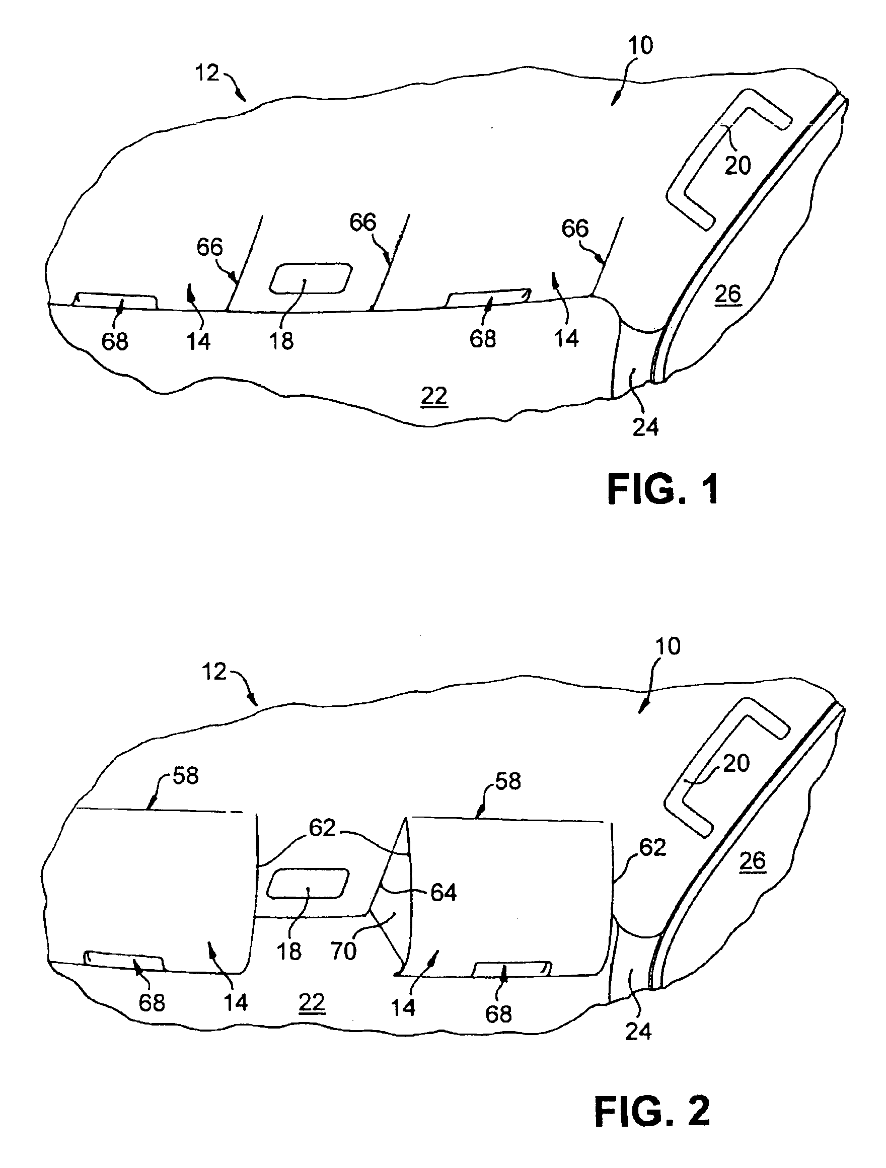
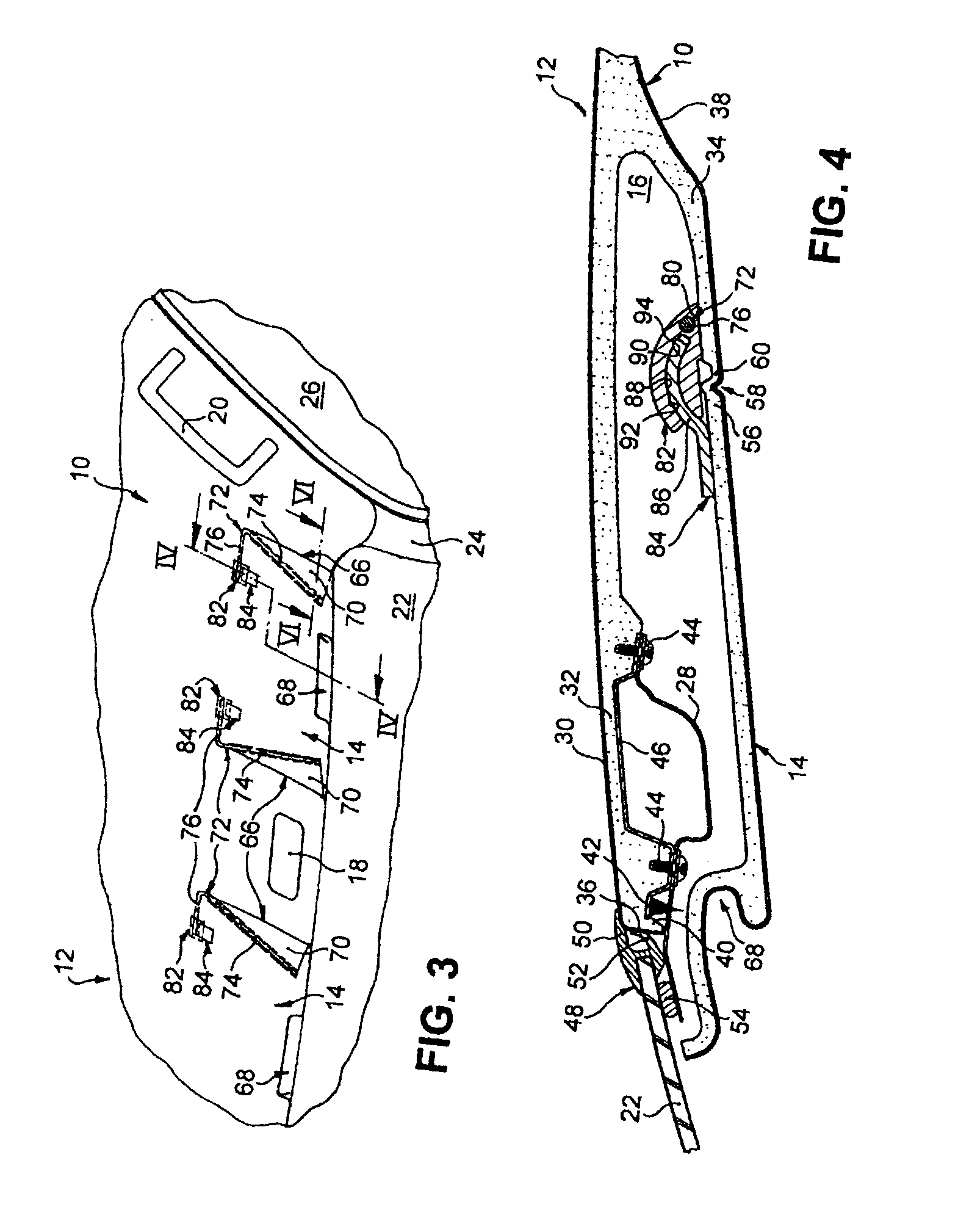
[0007]As a result, the flap in its non-usage position protrudes not at all or only very slightly over the inner shell in the thickness direction so that in particular when used as a sun visor on a vehicle roof or module, it does not additionally
restrict the
view angle of the driver and furthermore the vehicle interior can be optimized with regard to maximum head room for the driver or passenger. Also, the measures according to the invention achieve an optically refined outer appearance of the inner shell as the flaps to be provided on the inner shell for future reasons, in their non-usage positions do not
clutter undesirably, from a design aspect, the surface of the inner shell visible to the vehicle occupants. A further
advantage is that, because the flap is formed as part of the inner shell, the overall structure is simplified where a part which would otherwise have to be provided to structure the inner area trim of the vehicle, namely the inner shell, has at least one further function. Not least in regard to the total weight of the corresponding body part, the solution according to the invention can be considered advantageous: because the flap is formed as part of the inner shell, no additional part increasing the overall weight is required for the flap itself, as would be the case with conventional sun visor arrangements.
[0008]In one example, the flap is suitably connected to the inner shell at one edge via a hinge. The hinge viewed in the direction of travel of the vehicle lies in front of the flap serving as a sun visor, which has the
advantage that when the driver swivels the flap down from its non-usage position to shade the vehicle interior, the flap continuously narrows the
view angle. However, in a conventional arrangement of the hinge in which the hinge viewed in the direction of travel of the vehicle lies behind the flap serving as a sun visor, on a swivel movement of the flap from its non-usage position to its usage position. The conventional arrangement restricts the head room and causes an extreme restriction of view angle, during which it is difficult for the driver to observe
traffic conditions. In one example, the flap is formed as one piece with the inner shell, where the hinge is an advantageously simple manner is formed by a reduced-thickness section of the inner shell.
[0010]In one particular example, a guide device for the swivel movement of the flap is provided, which device has complementary intermeshing arc sections which provide the guidance and are arranged centered in relation to a swivel axis of the flap. Such a guide device ensures firstly a
good control sensation when the flap is swiveled out its non-usage position as the flap is not held merely by the hinge. Secondly, by suitable choice of the fit play between the arc sections of the guide device, a certain difficulty of movement of the swivel movement is achieved which depending on the relevant requirements allow the flap to be released in intermediate positions between its non-usage position and its usage position without the flap moving from its intermediate position due to its weight. In some embodiments, it is suitable for one arc section to be formed by a bearing shell foam-mounted on the flap, while the other arc section is formed by a bearing shell foam-mounted on the inner shell next to the flap, where one of the bearing shells has an arc-shaped slot which holds the arc-shaped end of the other bearing shell displaceably.
[0012]In another example between the side edges of the flap and adjacent edges of the inner shell are provided flexible side wall sections which by moving the flap from its non-usage position to its usage position can be tensioned into an essentially triangular
surface structure. When the reined flap is used as a sun visor on a vehicle roof or module, these side wall sections in the usage position of the flap advantageously prevent the lateral incidence of
sunlight into the vehicle interior (i.e., the incidence of
sunlight through the essentially triangular opening area) which in the usage position of the flap starting from the hinge extends in the height direction of the vehicle between the side edge of the flap and the adjacent edge of the inner shell. In an advantageously simple embodiment, these flexible side wall sections can be formed by a cover material which is in any case provided on the side of the inner shell facing the vehicle interior.
[0013]In another embodiment the flap is pretensioned in the non-usage position by means of at least one spring element which can be provided instead of or in addition to the guide or retaining device mentioned above. The spring element is required firstly for a
good control sensation when swiveling the flap down or out, as the spring element here ensures a defined operational resistance. When swiveling the flap up or in, the spring element advantageously aides the operator in the swivel movement. Secondly, the spring element ensures a defined end position of the flap in the non-usage position from which the flap cannot move independently or accidentally because of the spring pretension.
[0014]According to an advantageous refinement for such a spring device, two spring elements are provided which each act on one of the flexible side wall sections, where the spring elements pretension the side wall sections and hence the flap indirectly in the non-usage position. The spring elements here advantageously ensure that the flexible side wall sections assume a defined end position when the flap is in its non-usage position. In other words, on movement of the flap from the usage position to the non-usage position, the spring elements draw out the flexible side wall sections of the separating joints between the side edges of the flap and adjacent edges of the inner shell, so that the side wall sections cannot be damaged in the separating joints or hinder the swivel movement of the flap. In one example the spring elements are angled wire sections, each with a first leg which is fixed essentially central to the side wall section concerned, and a second leg, the free end of which is mounted rotatably in a bearing block which is foam-mounted onto the flap next to the inner shell. If both the spring elements and the guide device described below are provided, the bearing block for the spring element concerned and the bearing shell, foam-mounted onto the inner shell next to flap, for the guide device can advantageously easily be made of one piece.


