Micro surgical cutting instrument configured as scissors

a cutting instrument and micro-surgical technology, applied in the field of micro-surgical cutting instruments, can solve the problems of not meeting the requirements of modern micro-surgery, affecting the quality of life of the cutting instrument, and affecting the quality of life of the eye, etc., and achieves the effects of good visualization, easy to see, and no damag

Inactive Publication Date: 2005-06-21
ALCON INC
View PDF13 Cites 124 Cited by
  • Summary
  • Abstract
  • Description
  • Claims
  • Application Information

AI Technical Summary

Benefits of technology

[0008]In accordance with the invention, precise surgical procedures, without damage to the tissue when treating venous branch occlusions are realized with the cutting instrument. Use of the cutting instrument according to the invention is particularly advantageous for surgical procedures on the retina, for example for sub-retinal surgery.
[0009]In a further embodiment of the cutting instrument according to the invention, the instrument is provided with a light guide, which is axially disposed in the tube-shaped probe and connected at one end to a light source and at the other end is configured for illuminating the distal end of the cutting instrument specifically the two cutting blades that are projecting from the probe and facing each other in an open position or in closed position. The light guide is designed to illuminate the tip of the scissors, respectively the blade tips of the two cutting members during the surgical procedure, thereby illuminating the surgical field and rendering the tissue in the immediate area well visible.
[0010]For optimal handling of the instrument according to the invention, an optical channel provided with an optical guide is associated with the light guide in the probe. By means of this optical guide, images from the surgical field and the viewing field are transmitted to a monitor screen from initial insertion of the probe and for the duration of the surgical procedure. This particular embodiment of the instrument provides a good visualization of the surgical field making it easily visible for the operating surgeon so that exact surgical procedures in small organ cavities can be realized.
[0011]It is pointed out that the cutting instrument according to the invention is not limited to the field of ophthalmology and that the cutting instrument, without any modifications, can be used for a variety of surgical procedures in the body cavities of a living being. Without deviating from the basic idea of the invention, further modifications and embodiments of the cutting instrument and each of its functional elements is possible.

Problems solved by technology

For example, certain difficulties occur when treating the eye of a living being for retinal diseases.
The generally known prior art instruments have certain drawbacks such as, for example, they can damage the tissue due to improper configuration of the instrument's cutting blades; or, even prior to cutting the tissue, the blades can deform the tissue in a manner rendering it unsuitable for the cutting action, or the cutting blades unexpectedly retract during the procedure.
In many ways these known cutting instrument no longer fulfill the requirements of modern microsurgery and are not suited for surgery on delicate tissue structures, in particular for surgery on the delicate tissue of the retina.

Method used


Image

  • Micro surgical cutting instrument configured as scissors
  • Micro surgical cutting instrument configured as scissors
  • Micro surgical cutting instrument configured as scissors

Examples


Embodiment Construction

[0041]Throughout all the FIGURES, same or corresponding elements are generally indicated by same reference numerals.

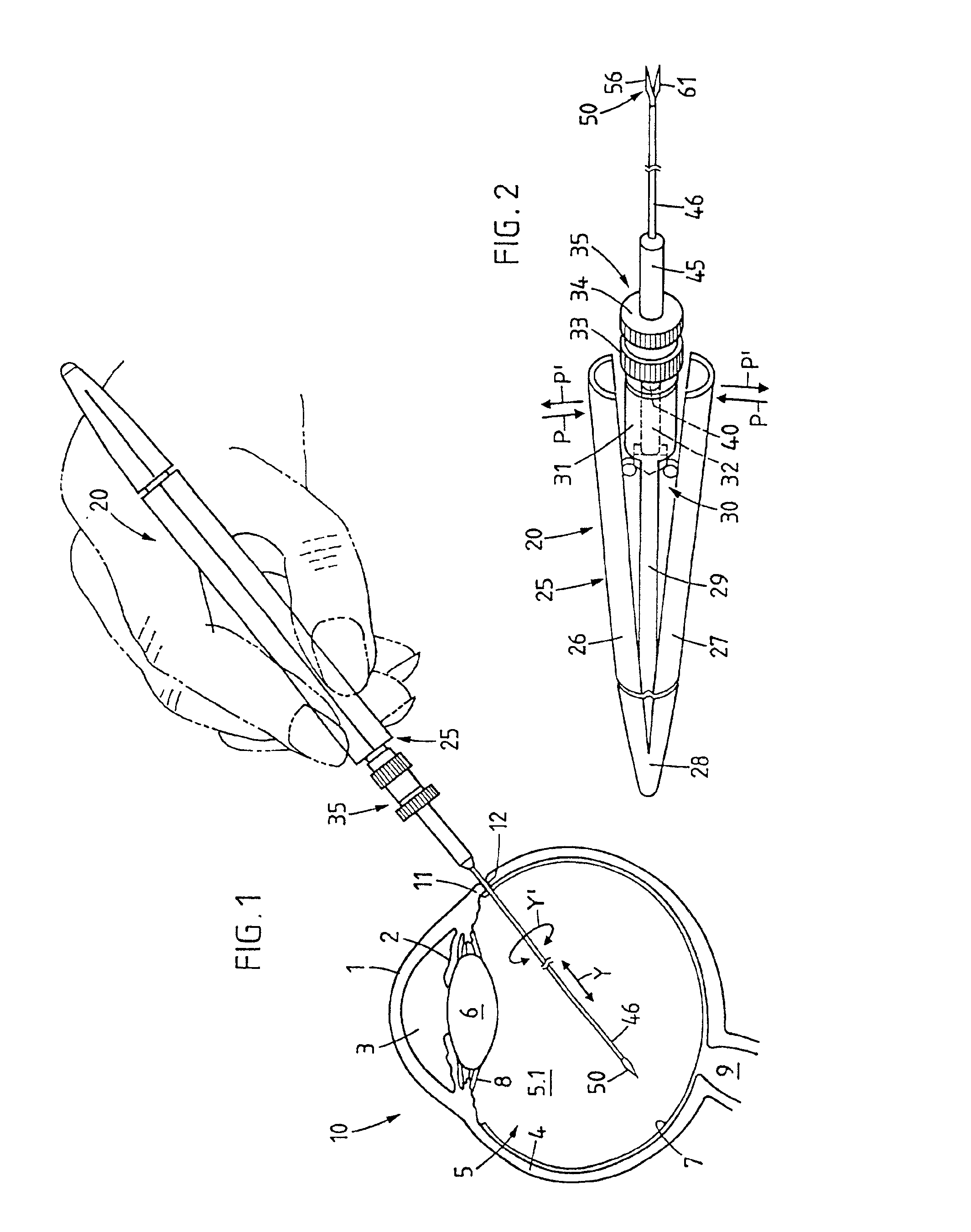
[0042]Turning now to FIG. 1, there is shown the horizontal section of an eye 10 on an enlarged scale, showing the cornea 1, the iris 2 with the pupilla 3, the sclera 4, and the vitreous humor 5 with the vitreous humor cavity 5.1 and lens 6, the retina 7 and the zonula fibers 8. The optic nerve bundle 9 (opticus), which projects from the eye, is schematically represented in the area of the eye background.

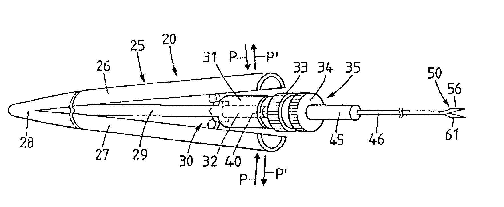
[0043]Further shown in FIG. 1 in schematic representation, is the cutting instrument 20, which is inserted into the space of the vitreous humor 5.1 of the eye by means of the probe 46, which is disposed on the instrument 20. The cutting instrument 20 comprises essentially a housing 25 which is operatively connected with a sliding unit not shown in detail in FIG. 1 and a functional unit 35 connected to probe 46, which is configured as a hollow needle. Disposed at the dis...


PUM


Abstract

A cutting instrument configured as scissors has a housing formed as a handle with a functional unit disposed therein; supported in the functional unit is a probe configured as a hollow needle which co-axially supports a rod projecting from the probe in axial direction and which comprises at its distal end a cutting device and wherein the cutting device has two cutting members provided with cutting blades that can be configured in an arc-shape or a straight shape, wherein from an open position the cutting blades correspond to each other at an acute angle, they are brought into engagement with each other to a closed position for a cutting action by means of a sliding movement of the probe relative to the scissors tip.

Description

BACKGROUND OF THE INVENTION[0001]The invention relates to a micro-surgical cutting instrument of the type configured as scissors, which includes a housing formed as a handle, and a device disposed in the housing for an axial sliding movement of a probe, that is configured as a hollow needle and which axially supports a rod with the cutting device disposed at the distal end of the rod.[0002]The present invention is generally directed to surgical procedures and special problems that occur when such procedures are carried out in body cavities of a living being. For example, certain difficulties occur when treating the eye of a living being for retinal diseases. Such diseases oftentimes appear in conjunction with hypertonia or vascular changes. In the course of such diseases, venous branch occlusions (phlebemphraxis) can occur in an area where veins and arteries cross each other and are surrounded by a substantially transparent skin sheath or membrane, whereby the artery which overlays ...

Claims


Application Information

Patent Timeline
Patent Type & Authority Patents(United States)
IPC IPC(8): A61B17/32A61F9/007A61B17/3211
CPCA61B17/320016A61B17/3201A61F9/007A61B2017/305
Inventor JUD, OLIVERMAAG, WERNER
Owner ALCON INC
Why Eureka
Try Eureka