Supercharge Your Innovation With Domain-Expert AI Agents!

System and method for increasing the strength of a bond made by a small diameter wire in ball bonding

a technology of ball bonding and small diameter wire, which is applied in the field of integrated circuits, can solve the problems of undesirable low bond strength, and achieve the effect of increasing the bond strength

Inactive Publication Date: 2005-06-21
STMICROELECTRONICS SRL
View PDF4 Cites 1 Cited by
  • Summary
  • Abstract
  • Description
  • Claims
  • Application Information

AI Technical Summary

Benefits of technology

The present invention provides an improved system and method for increasing the strength of a bond made to small diameter wires in a ball bonding process. This is achieved by using a structure that receives a wire bond, which includes a substrate material that has portions that form a substrate cavity and a wire bond pad metal that covers and fills the substrate cavity. The wire bond pad also has portions that form a wire bond cavity for receiving the ball bond. This structure provides additional strength to resist shear and tensile forces that may act on the wire bond. The invention also provides an improved method for providing a structure for receiving a wire bond. Overall, the invention enhances the reliability and durability of wire bonding processes.

Problems solved by technology

The lower bond strength is an undesirable feature.

Method used


Image

  • System and method for increasing the strength of a bond made by a small diameter wire in ball bonding
  • System and method for increasing the strength of a bond made by a small diameter wire in ball bonding
  • System and method for increasing the strength of a bond made by a small diameter wire in ball bonding

Examples


Embodiment Construction

[0026]FIGS. 1 through 8, discussed below, and the various embodiments used to describe the principles of the present invention in this patent document are by way of illustration only and should not be construed in any way to limit the scope of the invention. Those skilled in the art will understand that the principles of the present invention may be implemented for any suitably arranged integrated circuit.

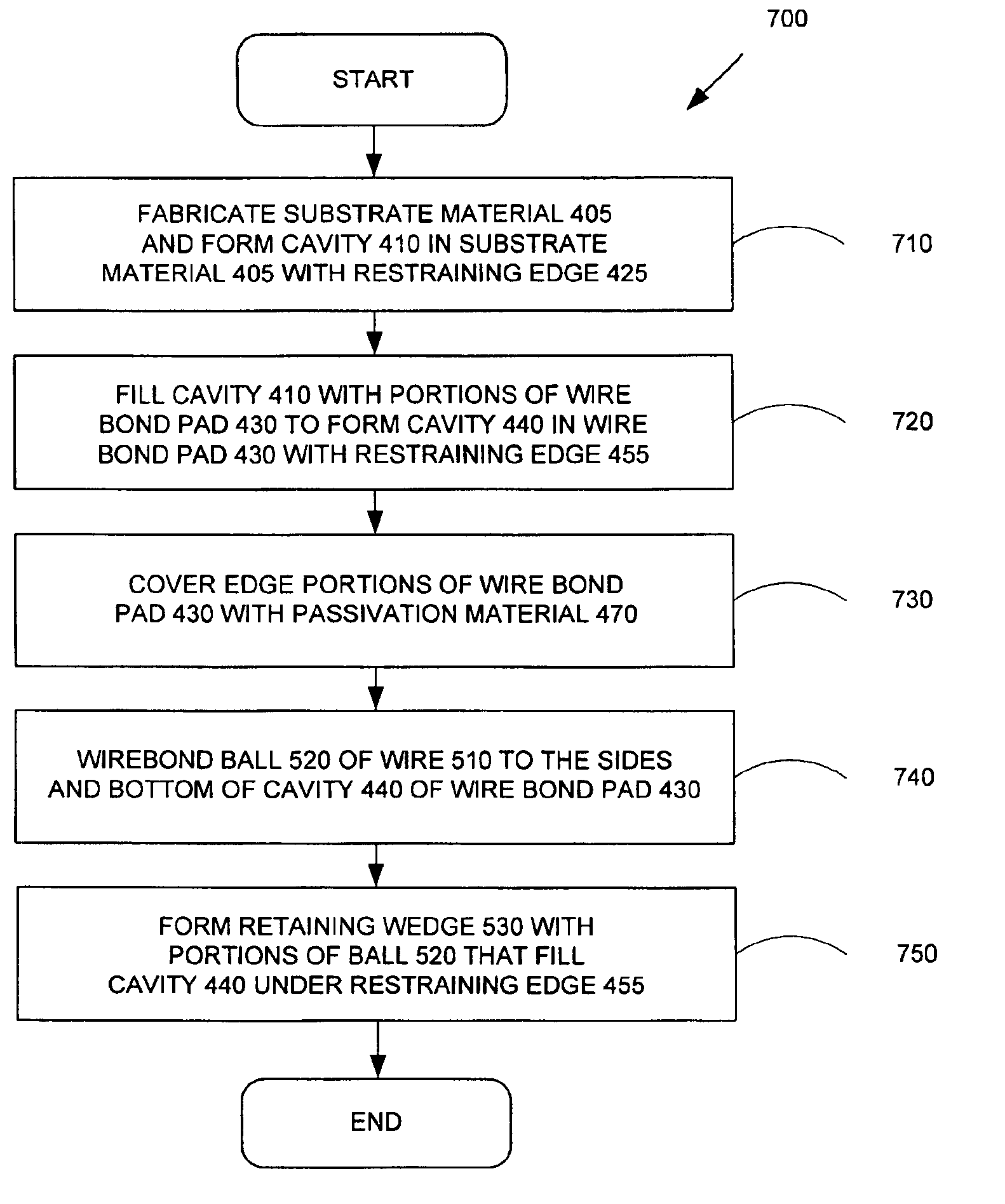
[0027]The system and method of the present invention provides increased bond strength between a ball bond of a small diameter wire and a wire bond pad in a ball bonding process for an integrated circuit chip.

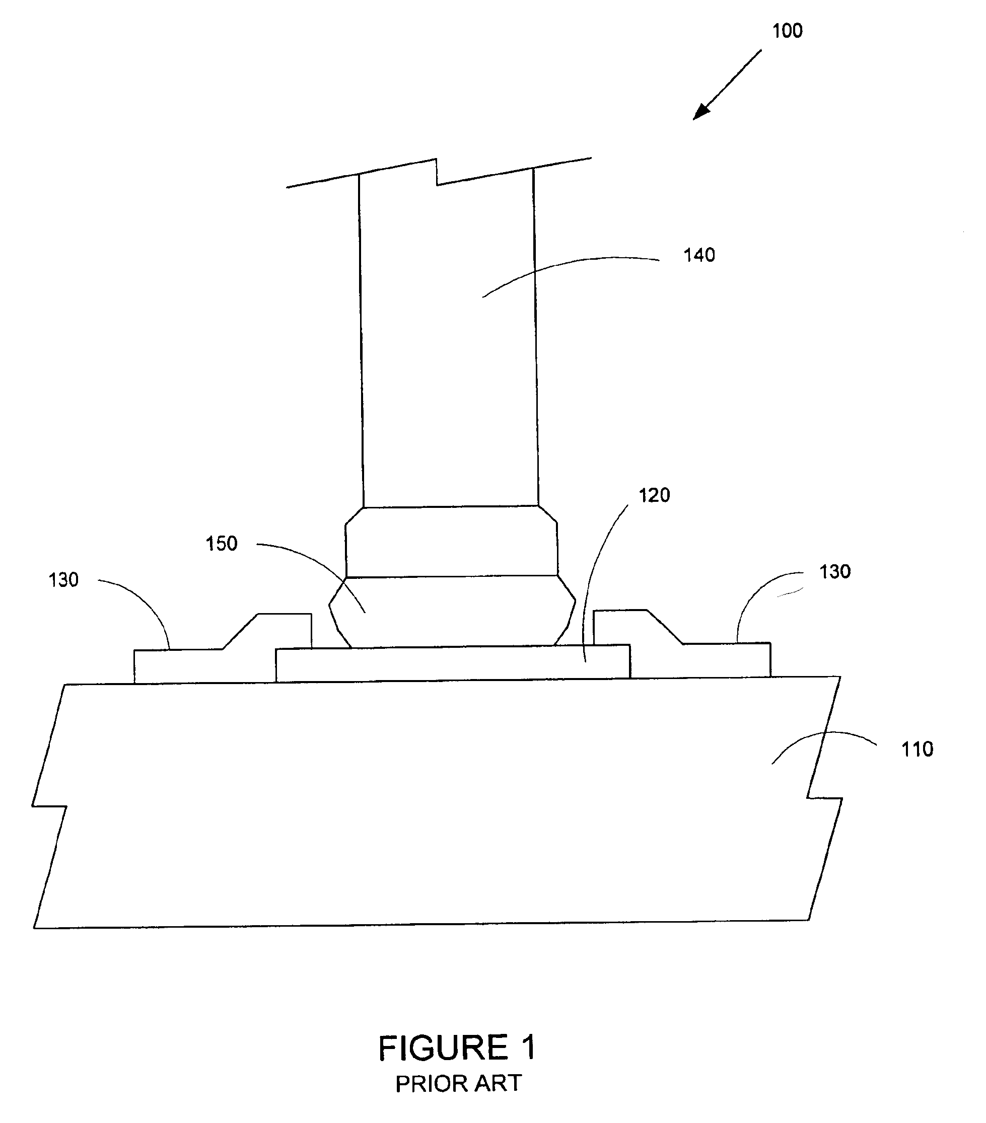
[0028]FIG. 1 illustrates a cross sectional view 100 of a prior art wire bond pad 120 and a prior art ball bond 150 of wire 140 bonded to the prior art wire bond pad 120. The features of prior art wire bond pad 120 have been previously discussed. Prior art wire bond pad 120 is flat. Prior art wire bond pad is placed on the surface of substrate material 110.

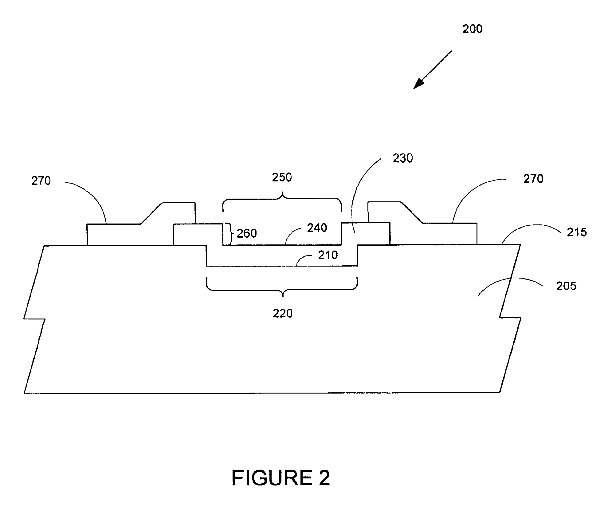
[0029]FIG. 2 illustrat...


PUM


Abstract

A system and method is disclosed for increasing the strength of a bond made by a small diameter wire in ball bonding. In one embodiment of the invention a structure for receiving a ball bond comprises substrate material that has portions that form a substrate cavity and a wire bond pad that covers and fills the substrate cavity. The wire bond pad also has portions that form a wire bond cavity for receiving the ball bond. The ball is wirebonded to the sides and bottom of the wire bond cavity. The sides of the wire bond cavity provide additional strength to the bond to resist shear and tensile forces that may act on the wire.

Description

TECHNICAL FIELD OF THE INVENTION[0001]The present invention is directed, in general, to integrated circuits and, more specifically, to a system and method for increasing the strength of a bond made by a small diameter wire in a ball bonding process.BACKGROUND OF THE INVENTION[0002]Wirebonding is a well known electrical interconnection technique used in the manufacture of integrated circuits and other microelectronic structures. For example, the input / output (I / O) wires of an integrated circuit chip may be wirebonded to their respective wire bond pads on the integrated circuit chip.[0003]Wirebonding is a solid phase welding process that welds the metallic material of a wire to the metallic material of a corresponding wire bond pad. After a wire and a wire bond pad are placed in contact, the wire and the wire bond pad may be welded together using a well known process such as a thermocompression process, an ultrasonic process, or a thermosonic process.[0004]There are two basic forms of...

Claims


Application Information

Patent Timeline
Patent Type & Authority Patents(United States)
IPC IPC(8): H01L23/485H01L23/48H01L21/60
CPCH01L24/03H01L24/05H01L24/48H01L24/85H01L24/45H01L2224/02126H01L2224/02166H01L2224/04042H01L2224/05009H01L2224/05556H01L2224/05558H01L2224/05624H01L2224/05647H01L2224/45015H01L2224/45124H01L2224/45144H01L2224/45147H01L2224/48091H01L2224/48227H01L2224/48237H01L2224/48463H01L2224/48472H01L2224/48624H01L2224/48647H01L2224/48724H01L2224/48747H01L2224/48824H01L2224/48847H01L2224/4943H01L2224/85365H01L2924/01004H01L2924/01006H01L2924/01013H01L2924/01014H01L2924/01029H01L2924/01033H01L2924/01079H01L2924/01082H01L2924/10157H01L2924/14H01L2924/20752H01L2924/20753H01L2924/00014H01L2224/48453H01L2224/73265H01L2224/78H01L2924/00H01L24/49H01L2224/85203H01L2224/85205H01L2224/85207H01L2924/181H01L2924/00012
Inventor CHIU, ANTHONY M.
Owner STMICROELECTRONICS SRL
Features
  • R&D
  • Intellectual Property
  • Life Sciences
  • Materials
  • Tech Scout
  • Unparalleled Data Quality
  • Higher Quality Content
  • 60% Fewer Hallucinations
Learn More