

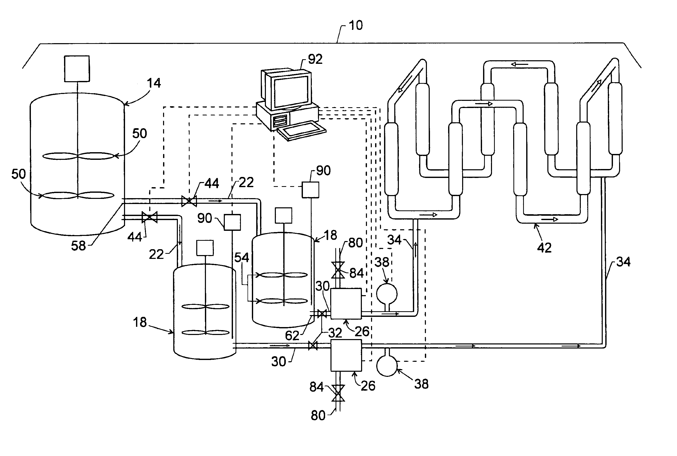
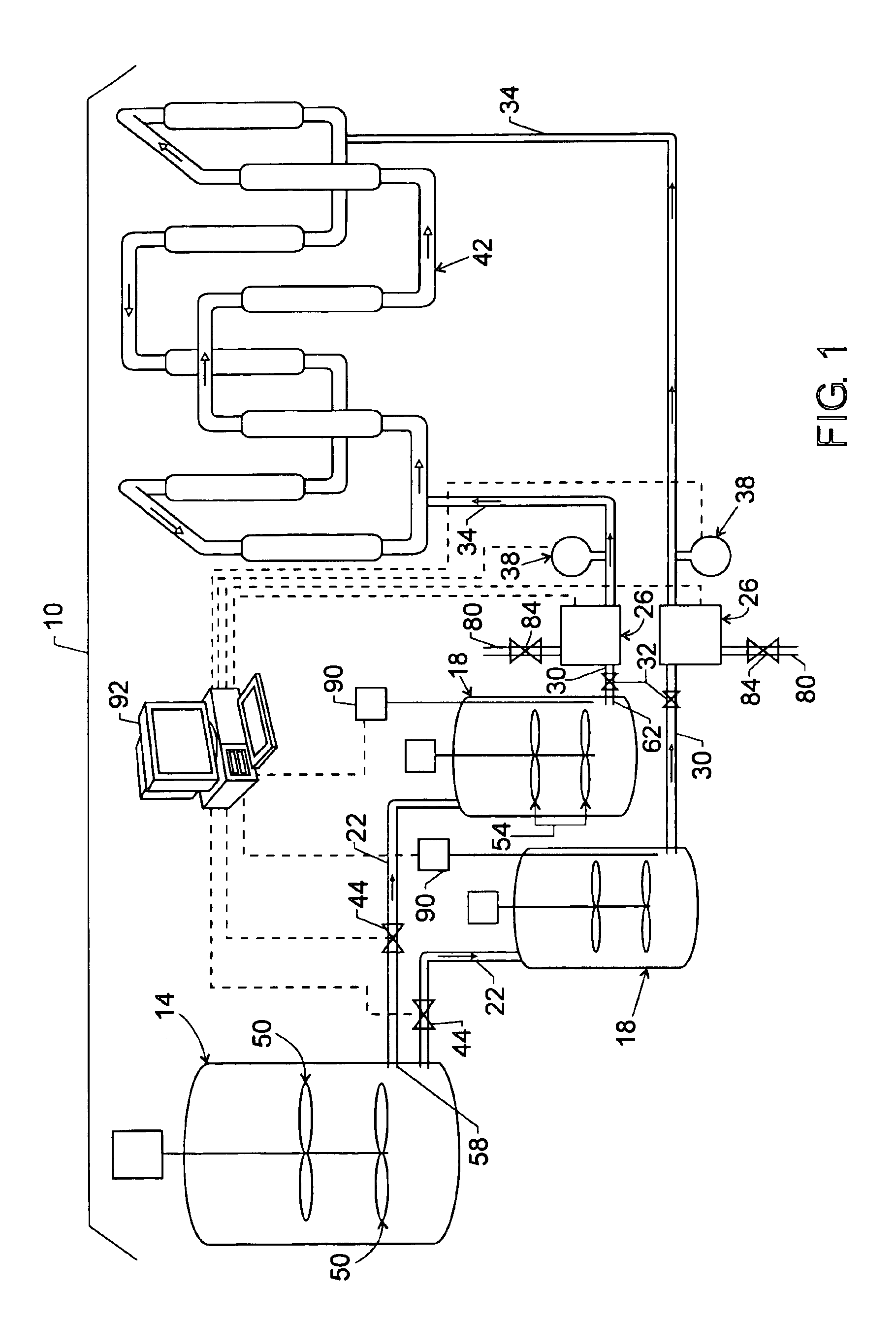
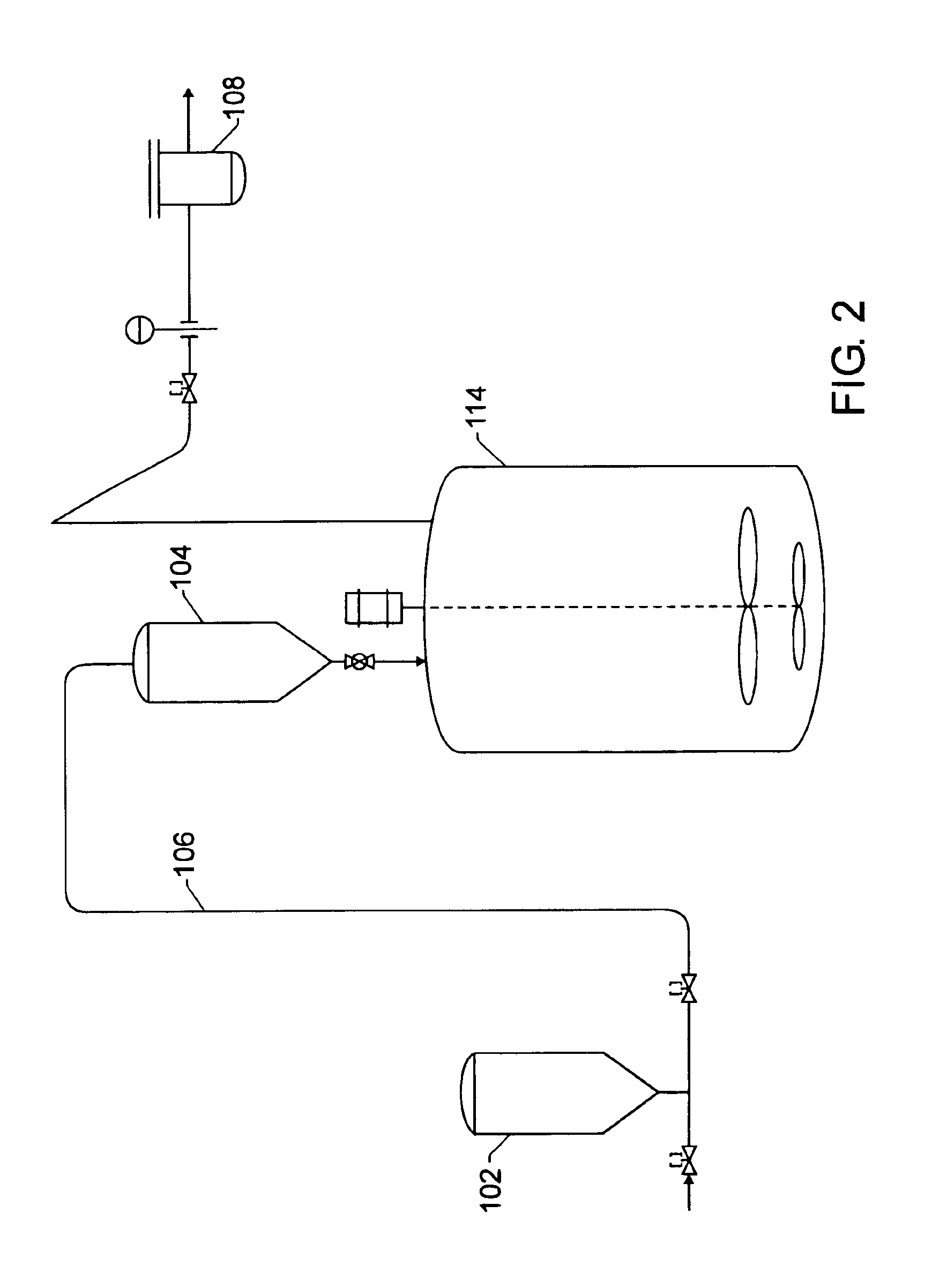
Catalyst slurry feeding assembly for a polymerization reactor
- Summary
- Abstract
- Description
- Claims
- Application Information
AI Technical Summary
Benefits of technology
Problems solved by technology
Method used
Image

Examples
Embodiment Construction
[0023]The processes and apparatus are particularly applicable to olefin polymerizations in a liquid medium. Suitable olefin monomers are 1-olefins having up to 8 carbon atoms per molecule and no branching nearer the double bond than the 4-position. The present processes and apparatus may be used with a loop reactor for the copolymerization of ethylene and a higher 1-olefin such as butene, 1-pentene, 1-hexene, 1-octene and 1-decene. For example, the present processes and apparatus may be used to polymerize ethylene and 0.01 to 10 weight percent higher-olefin, alternatively 0.01 to 5 weight percent higher-olefin, alternatively 0.1 to 4 weight percent higher 1-olefin, based on the total weight of ethylene and comonomer. Alternatively sufficient comonomer can be used to give the above-described amounts of comonomer incorporation in the polymer.
[0024]The liquid medium may be a diluent for the solid polymer particles that is separate from and in addition to the unreacted monomers. Suitabl...
PUM
| Property | Measurement | Unit |
|---|---|---|
| Pressure | aaaaa | aaaaa |
| Flow rate | aaaaa | aaaaa |
| Ratio | aaaaa | aaaaa |
Abstract
Description
Claims
Application Information