
Transfer ribbon, image expressing medium and method for production of them

Active Publication Date: 2005-06-21
DAI NIPPON PRINTING CO LTD
View PDF4 Cites 26 Cited by
  • Summary
  • Abstract
  • Description
  • Claims
  • Application Information

AI Technical Summary

Benefits of technology

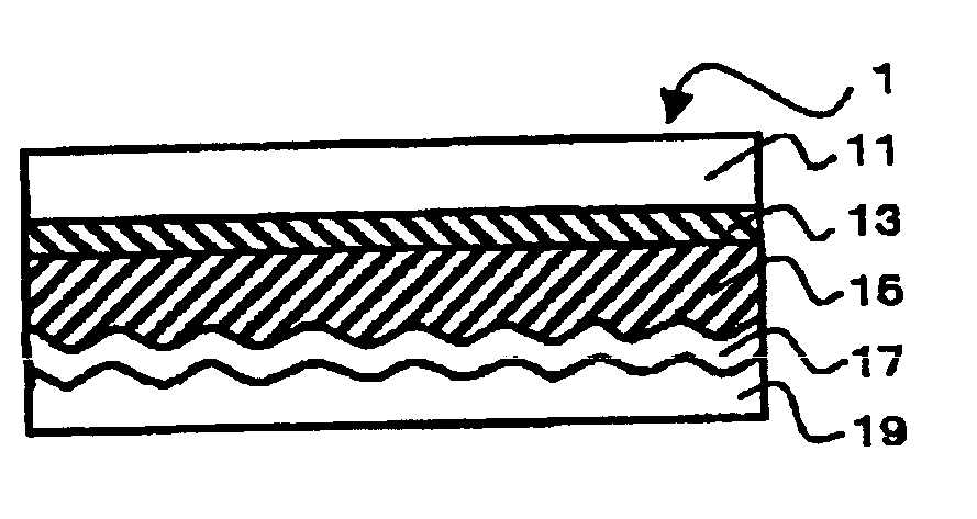
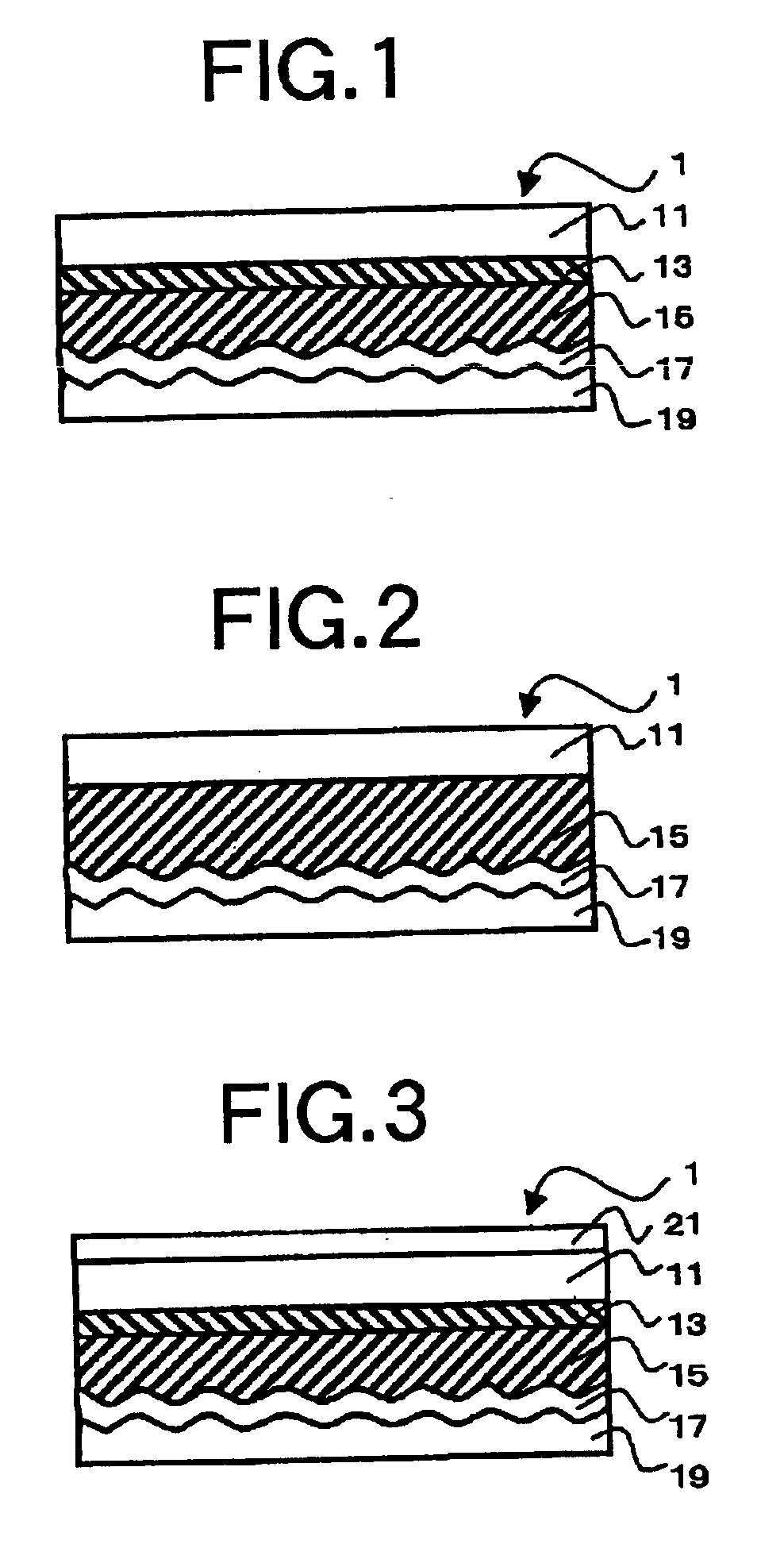
[0012]A first object of the present invention is to provide a transfer ribbon which can transfer dots having minute area or dots closing with each other without any burr, lack nor chipping of dots even by using a thermal head of a thermal printer.
[0037]A frame of an image such as pattern or photograph on the image expressing medium can be made so as to have gradation design or various figures depending on arrangement and / or combination of dots, so that the image expressing medium can exhibits visual designs with particularly high quality such as lame-like glittering effect.

Problems solved by technology

A transfer ribbon (transfer foil) provided with a transferable layer having relief structures such as holograms or diffraction gratings can print and express specially decorated images or three-dimensional images, and it can also produce a printed product hard to be forged or duplicated because the hologram and the diffraction grating require high technology for producing themselves and they are therefore difficult to be produced.
However, the hot stamping method and the thermal transfer method using the heating roller cause a problem of difficulty in precise transfer of fine patterns such as dots having minute areas smaller than several millimeter square (mm2) or dots being present close to each other.
A method to form such fine patterns includes an etching method, but it requires many processes so that it takes longer time and much cost.
Moreover, conventional transfer ribbons have low sensitivity toward instantaneous heating by a thermal head, so that they provide very low printing speed and further provide faults of causing lacks or chipping of the dots to be transferred on a transfer-receiving material or causing burrs, that is, layers being transferred and left in areas between the dots on the transfer-receiving material.
However, the above mentioned method requires a number of transfer ribbons and multiple transfer processes.
In addition, a conventional transfer ribbon is involved with a fault of considerable difficulty in transferring fine dots without causing burrs and lacks of dots.

Method used


Image

  • Transfer ribbon, image expressing medium and method for production of them
  • Transfer ribbon, image expressing medium and method for production of them
  • Transfer ribbon, image expressing medium and method for production of them

Examples


examples

[0259]Hereinafter, the present invention will be explained more in detail, with reference to preparation examples of ionizing radiation-curable resin, experimental examples of the transfer ribbons, those of the image expressing medium and their comparative examples.

[0260]In the description, all designations of “parts” and “%” indicate parts by weight and weight percentage (wt. %), respectively, unless otherwise noted.

[0261]First, the examples of preparing urethane modified acrylic resins (ionizing radiation-curable resin) which were used in the present invention are described.

Preparation Example of Ionizing Radiation-Curable Resin A

[0262]Into a 2 liter four-necked flask equipped with a cooling condenser, a dropping funnel and a thermometer, 40 g of toluene, 40 g of methylethylketone (MEK), and an azo-type initiator were put. Next, a mixed solution consisting of 24.6 g of 2-hydroxyethylmethacrylate (HEMA), 73.7 g of methylmethacrylate (MMA), 24.6 g of dicyclopentenyloxyethylmethacryl...

example a series

[0292]Next, the transfer ribbons according to the present invention will be described in more detail with reference to the following Example A series.

example a1

[0293]As a substrate, a polyethylene terephthalate film (trademark: F-53, Toray Industries, Inc.) with thickness of 6 μm is used, and a heat-resistant protection layer listed in the Table A1 was formed on one surface thereof prior to formation of a peelable layer.

[0294]Onto a surface of the substrate opposite to that having the heat-resistant protection layer, the peelable layer forming composition(ink) A was applied by means of a roll coater at a film speed of 50 m / min and then dried at 80° C. to form a peelability-potential layer with thickness of 0.5 μm in dried state.

[0295]Next, onto the peelability-potential layer, the relief layer forming composition(ink) A was applied by means of a gravure reverse coater at a film speed of 50 m / min and then dried at 100° C. to form a relief forming layer with thickness of 0.5 μm in dried state. The obtained film was not adhesive at ambient temperature, and accordingly it could be stored or processed in its rolled state.

[0296]On the other hand...


PUM

PropertyMeasurementUnit
Percent by massaaaaaaaaaa
Areaaaaaaaaaaa

Abstract

The invention provides a transfer ribbon having a layered structure in which a substrate, a relief layer and a reflection layer are laminated in this order, wherein the relief layer comprises an ionizing radiation-cured resin. The transfer ribbon can precisely transfer fine dots and / and dots placed close to each other with a low energy and at a high speed without any of burrs, chippings or lacks by means of a thermal head. Also, the invention provides an image expressing medium, which can be produced using the transfer ribbon described above, and comprises a support, a color layer and plural dots of relief hologram and / or diffraction grating. In the medium: the color layer and the dots are disposed on the same surface of the support; and the each dot has an area in a range from 0.0001 to 0.09 mm2; the each dots has a diffraction direction different from that of at least one of adjacent dots, or the dot has two or more sections each of which has a diffraction direction different from each other. The image expressing medium exhibits specially decorative effects such as a lame-like effect.

Description

BACKGROUND OF THE INVENTION[0001]1. Field of the Invention[0002]The present invention relates to a transfer ribbon and a method for production of the transfer ribbon, and particularly relates to a transfer ribbon which has a transferable layer (relief layer) with a relief structure such as hologram and / or diffraction grating and is available for transferring the relief layer in a fine pattern by means of a thermal head, and a method of production of such a transfer ribbon.[0003]The present invention also relates to an image expressing medium and a method for production thereof, and particularly relates to an image expressing medium having an image which contains plural dots of the relief layer transferred from the above described transfer ribbon and can exhibit a lame-like glittering effect based on the dots, and a method of production of such an image expressing medium.[0004]2. Description of the Related Art[0005]A transfer ribbon (transfer foil) provided with a transferable layer ...

Claims


Application Information

Patent Timeline
IPC IPC(8): B41J2/325B41M5/40B41M5/42B41J31/00B41M5/382
CPCB41J2/325B41M5/38214B41M5/42G03H1/0252G03H1/0476G03H1/0244G03H2001/0284G03H2230/10G03H2250/10G03H2250/34G03H2250/35G03H2250/36G03H2270/23G03H2001/0497
Inventor ISHIDA, TADAHIROMIZUKAMI, FUMIHIKO
Owner DAI NIPPON PRINTING CO LTD
Learn More