Speech signal decoding method and apparatus, speech signal encoding/decoding method and apparatus, and program product therefor

a speech signal and decoding technology, applied in the field of speech signal decoding methods and apparatus, can solve problems such as abnormal sound produced in noise segments

Inactive Publication Date: 2005-06-21
NEC CORP
View PDF8 Cites 30 Cited by
  • Summary
  • Abstract
  • Description
  • Claims
  • Application Information

AI Technical Summary

Benefits of technology

[0051]Accordingly, an object of the present invention in one aspect thereof is to provide an apparatus and method, and a program product as well as a medium on which the related program has been recorded, through which it is possible to avoid the occurrence of abnormal sound in noise segments, such sound being caused when, in the smoothing of sound source gain (the second gain), the sound source gain smoothed in a noise segment takes on a value much larger than that of the sound source gain before smoothing.

Problems solved by technology

A problem with the conventional coder and decoder described above is that there are instances where an abnormal sound is produced in noise segments when the sound source gain (the second gain) is smoothed.

Method used


Image

  • Speech signal decoding method and apparatus, speech signal encoding/decoding method and apparatus, and program product therefor
  • Speech signal decoding method and apparatus, speech signal encoding/decoding method and apparatus, and program product therefor
  • Speech signal decoding method and apparatus, speech signal encoding/decoding method and apparatus, and program product therefor

Examples


first embodiment

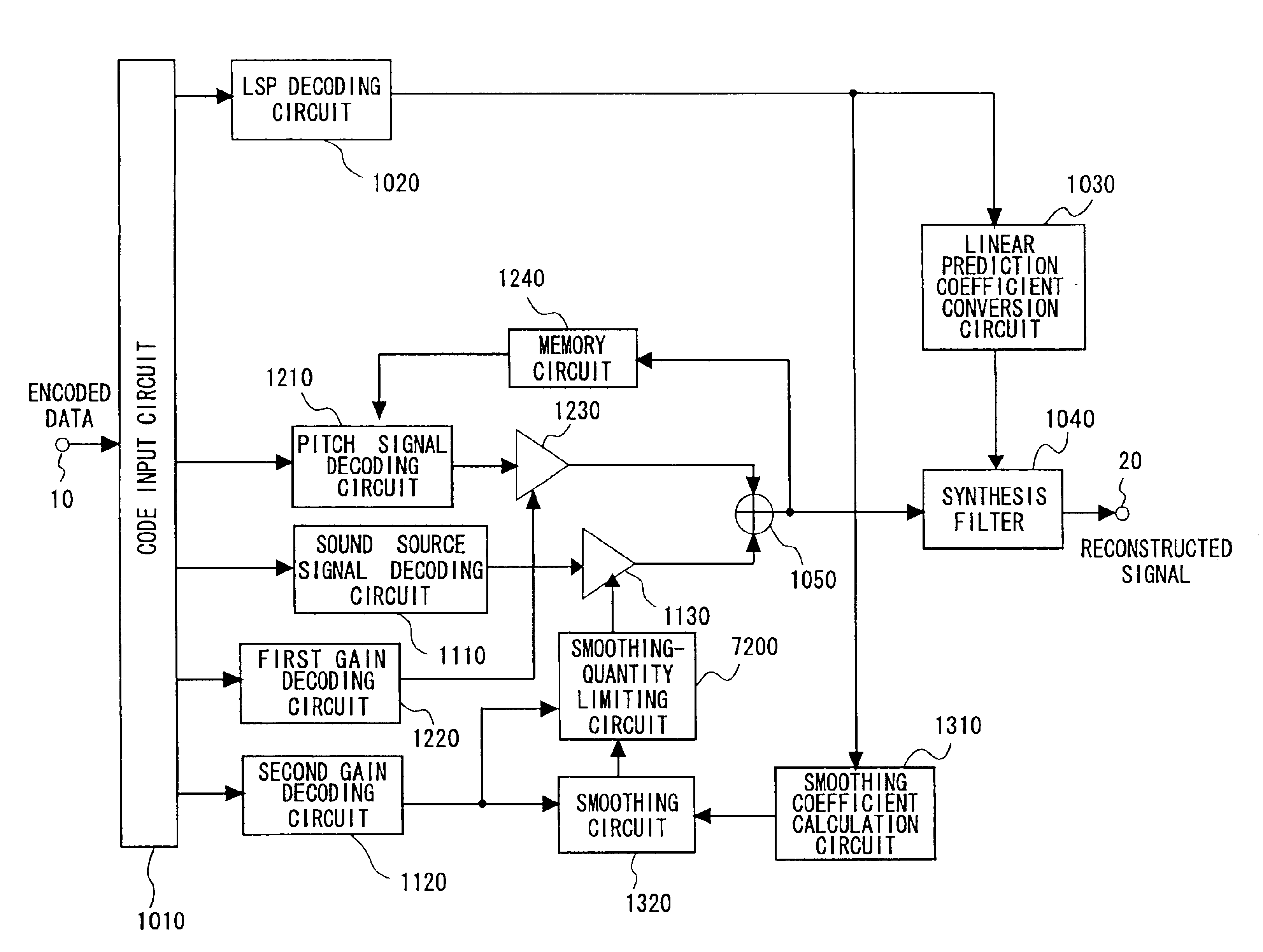
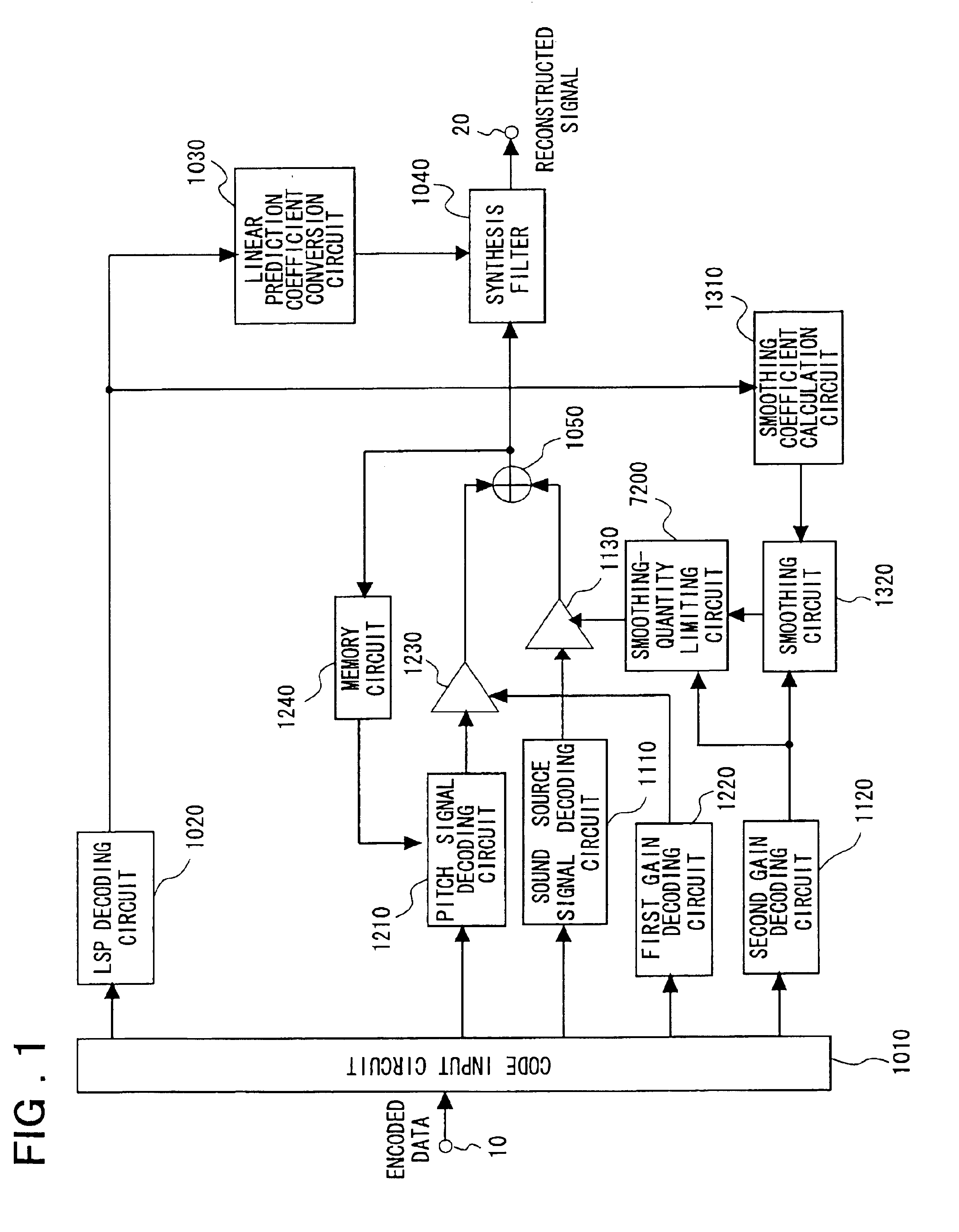
[0101]FIG. 1 is a block diagram illustrating the construction of a speech signal decoding apparatus according to the present invention. Components in FIG. 1 identical with or equivalent to those shown in FIG. 8 are identified by like reference characters.

[0102]In FIG. 1, the input terminal 10, output terminal 20, code input circuit 1010, LSP decoding circuit 1020, linear prediction coefficient conversion circuit 1030, sound source signal decoding circuit 1110, memory circuit 1240, pitch signal decoding circuit 1210, first gain decoding circuit 1220, second gain decoding circuit 1120, first gain circuit 1230, second gain circuit 1130, adder 1050, smoothing coefficient calculation circuit 1310, smoothing circuit 1320 and synthesis filter 1040 are identical with the similarly identified components shown in FIG. 8 and need not be described again. The entire description made in the introductory part of this application with respect to FIG. 8 is hereby incorporated as part of the disclosu...

second embodiment

[0116]the present invention will now be described.

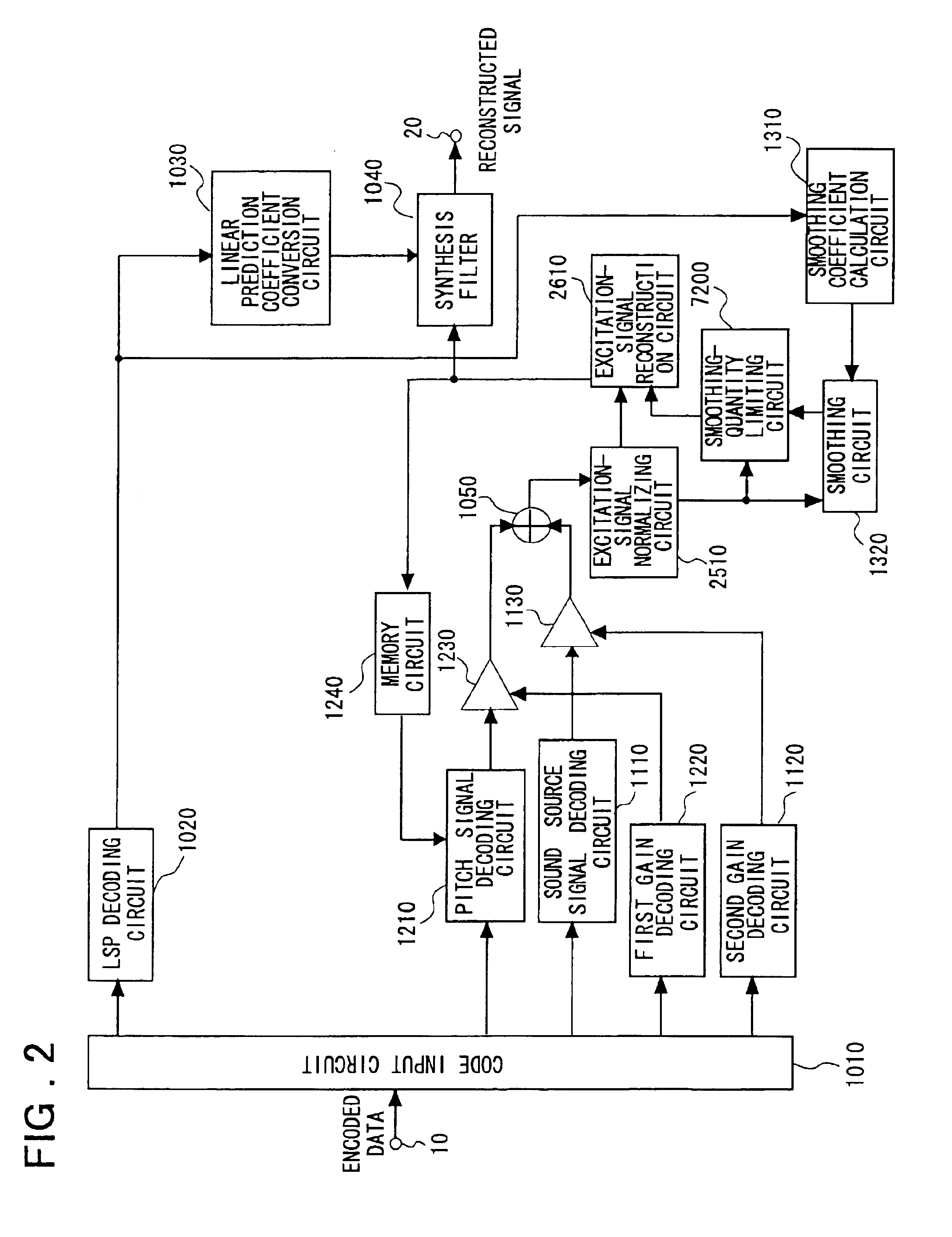
[0117]FIG. 2 is a block diagram illustrating the construction of a speech signal decoding apparatus according to a second embodiment of the present invention. Components in FIG. 2 identical with or equivalent to those shown in FIGS. 1 and 8 are identified by like reference characters.

[0118]As shown in FIG. 2, the second embodiment is so adapted that the norm of the excitation vector is smoothed instead of the decoded sound source gain (the second gain) as in the first embodiment. It should be noted that the input terminal 10, output terminal 20, code input circuit 1010, LSP decoding circuit 1020, linear prediction coefficient conversion circuit 1030, sound source signal decoding circuit 1110, memory circuit 1240, pitch signal decoding circuit 1210, first gain decoding circuit 1220, second gain decoding circuit 1120, first gain circuit 1230, second gain circuit 1130, adder 1050, smoothing coefficient calculation circuit 1310, smoothin...

third embodiment

[0124]the present invention will now be described.

[0125]FIG. 3 is a block diagram illustrating the construction of a speech signal decoding apparatus according to a second embodiment of the present invention. Components in FIG. 3 identical with or equivalent to those shown in FIGS. 2 and 8 are identified by like reference characters. The input terminal 10, output terminal 20, code input circuit 1010, LSP decoding circuit 1020, linear prediction coefficient conversion circuit 1030, sound source signal decoding circuit 1110, memory circuit 1240, pitch signal decoding circuit 1210, first gain decoding circuit 1220, second gain decoding circuit 1120, first gain circuit 1230, second gain circuit 1130, adder 1050, smoothing coefficient calculation circuit 1310, smoothing circuit 1320 and synthesis filter 1040 are identical with the similarly identified components shown in FIG. 8, and the excitation-signal normalizing circuit 2510 and excitation-signal reconstruction circuit 2610 are ident...


PUM


Abstract

The quality of reconstructed speech on which background noise is superimposed is improved in a speech signal decoding apparatus for generating a speech signal by driving a filter, which is constituted by linear prediction coefficients, by an excitation signal. A smoothing circuit smoothes sound source gain in a noise segment using sound source gain that was obtained in the past. A smoothing-quantity limiting circuit calculates an amount of fluctuation represented by dividing, by the sound source gain, the absolute value of the difference between the sound source gain and the sound source gain that has been smoothed, and limits the value of the smoothed gain in such a manner that the amount of fluctuation will not exceed a certain threshold value.

Description

FIELD OF THE INVENTION[0001]This invention relates to a method of encoding and decoding a speech signal at a low bit rate. More particularly, the invention relates to a speech signal decoding method and apparatus, a speech signal encoding / decoding method and apparatus and a program product for improving the quality of sound in noise segments.BACKGROUND OF THE INVENTION[0002]A method of encoding a speech signal by separating the speech signal into a linear prediction filter and its driving excitation signal (excitation signal, excitation vector) is used widely as a method of encoding a speech signal efficiently at medium to low bit rates. One such method that is typical is CELP (Code-Excited Linear Prediction). With CELP, a linear prediction filter for which linear prediction coefficients representing the frequency characteristic of input speech have been set is driven by an excitation signal (excitation vector) represented by the sum of a pitch signal (pitch vector), which represent...

Claims


Application Information

Patent Timeline
Patent Type & Authority Patents(United States)
IPC IPC(8): G10L21/00G10L19/08G10L21/02G10L19/00G10L19/06G10L19/12H03M7/30
CPCG10L21/0364G10L19/083G10L2019/0012
Inventor MURASHIMA, ATSUSHI
Owner NEC CORP
Why Eureka
Try Eureka