Nitrogen generator

a generator and nitrogen technology, applied in the direction of liquefaction, separation process, lighting and heating apparatus, etc., can solve the problems of unsuitable nitrogen flow, unfavorable liquefaction, and high cost of liquefaction equipment, so as to improve efficiency and rapid assembly, improve efficiency, and provide further stability.

Inactive Publication Date: 2005-06-28
PACIFIC CONSOL INDS
View PDF13 Cites 11 Cited by
  • Summary
  • Abstract
  • Description
  • Claims
  • Application Information

AI Technical Summary

Benefits of technology

[0013]Another aspect of the present invention includes the realization that standard sized containers can be used to provide a protective housing during transportation and operation of the cryogenic nitrogen generator. By using standard size containers to form a housing for a cryogenic nitrogen generator, such as a cryogenic distillation and associated heat exchanger unit, the device can be shipped to a drilling site and efficiently and quickly assembled into an operative state. For example, a cryogenic nitrogen generator can include an air preparation unit and a cryogenic distillation and associated heat exchanger unit. The air preparation unit typically will include an absorption device, such as a Pressure Swing Absorption (PSA) or a Temperature Swing Absorption (TSA) unit. Optionally, the air preparation unit can also include one or a plurality of air compressor units. The air preparation unit can be configured to fit within a standard ISO container resting horizontally. However, a cryogenic distillation unit is quite tall. For example, typical cryogenic distillat

Problems solved by technology

One drawback of non-cryogenic devices is that efficiency drops off rapidly as purity increases.
However, these units are not practical for generating

Method used


Image

  • Nitrogen generator
  • Nitrogen generator
  • Nitrogen generator

Examples


Embodiment Construction

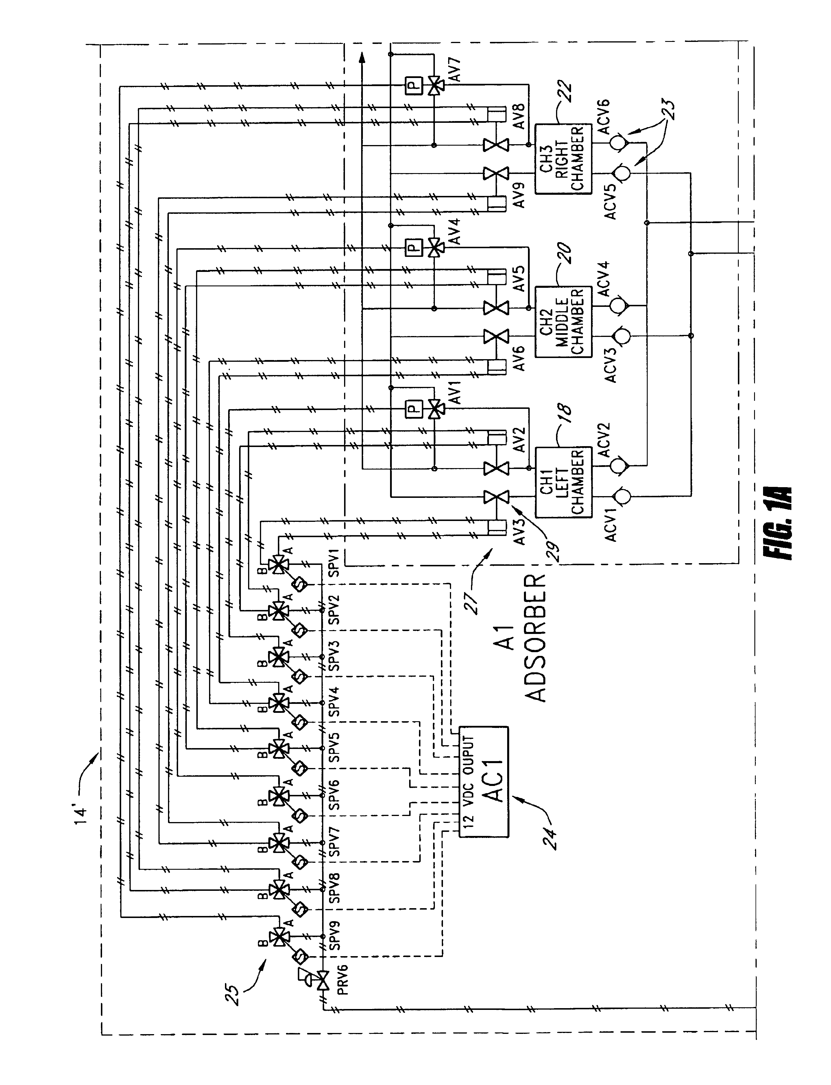
[0025]With reference to FIG. 1, a gas separation unit, constructed in accordance with one aspect of the present invention, is illustrated therein identified by the reference numeral 10. The gas separation unit 10 comprises an air source 12, an absorption unit 14, and a cryogenic distillation unit 16.

[0026]The air source 12 can be in the form of any source of air. Preferably, the air source 12 is an air compressor configured to pressurize air. Any commercially available air compressor can be used for the air source 12. For example, the air source 12 can be a centrifugal, dry or lubricated screw, or reciprocating-type air compressor. If an oil-lubricated system is used, additional equipment can be used to remove oil droplets and vapors formed during the compression process.

[0027]The absorption unit 14 can be in the form of a pressure swing absorption (PSA) or a temperature swing absorption (TSA) system. Preferably, the absorption unit 14 is configured to remove water vapor, carbon dio...


PUM

PropertyMeasurementUnit
Lengthaaaaaaaaaa
Fractionaaaaaaaaaa
Fractionaaaaaaaaaa

Abstract

A portable cryogenic nitrogen generator consists of an air preparation unit and a cryogenic distillation unit mounted inside separate standard-sized ISO containers that can be easily shipped to a drilling site and efficiently and quickly assembled into an operative state. The containers can be connected together at anchor points on the housings of both containers, making the nitrogen generator assembly more stable. The air preparation unit includes an absorption device and optionally includes one or a plurality of air compressor units. The cryogenic distillation unit includes a distillation column and associated heat exchangers. The air preparation and cryogenic distillation units connect through apertures in their respective containers and operate while being mounted in the containers.

Description

RELATED CASES[0001]This application is based on and claims priority to U.S. Provisional Patent Application Ser. No. 60 / 402,878, filed Aug. 8, 2002, the entire contents of which is hereby incorporated by reference.BACKGROUND OF THE INVENTION[0002]1. Field of the Invention[0003]The present invention is directed to nitrogen generators, and in particular, portable cryogenic nitrogen generators.[0004]2. Description of the Related Art[0005]Inert gases are widely used in many industrial processes. For example, nitrogen gas is commonly used in conjunction with operation of a drilling rig for oil, gas, or geothermal wells, as well as for post drilling operations. In particular, nitrogen is injected into the down-hole region during a drilling operation, to remove drill cuttings.[0006]In the art of well drilling, tubular casings are typically inserted into the wells so as to secure the perimeter of the wellbore. In some wells, multiple casings are secured at the surface of the well to lower do...

Claims


Application Information

Patent Timeline
IPC IPC(8): F25J3/04
CPCF25J3/04254F25J3/04284F25J3/044F25J3/04824F25J3/0489F25J3/04975Y10S62/911F25J2205/60F25J2205/82F25J2210/42F25J2290/70F25J3/04818F25J3/0486
Inventor BRIGHAM, WILLIAM D.WILDEY, BRIAN R.ZARATE, ROBERT A.
Owner PACIFIC CONSOL INDS
Why Eureka
Try Eureka