
HCCI engine with combustion-tailoring chamber

a technology of combustion tailing and engine, which is applied in the direction of machines/engines, mechanical equipment, non-mechanical valves, etc., can solve the problems of egr control, too long response time, and limited hcci operation reported by egr as control, and achieve the effect of fast control of the hcci combustion process

Inactive Publication Date: 2005-06-28
ENVIRONMENTAL PROTECTION AGENCY US
View PDF8 Cites 10 Cited by
  • Summary
  • Abstract
  • Description
  • Claims
  • Application Information

AI Technical Summary

Benefits of technology

[0010]This invention utilizes a variable compression ratio along with EGR to control HCCI operation. A variable compression ratio is achieved by using an auxiliary volume connected to the main combustion chamber through a port with a control valve located in the port. The timing of the control valve, which can be adjusted from one engine cycle to another, if necessary, enables the present invention to provide much faster response as compared to the prior art.
[0011]In the present invention, the control valve is operated in such a way that the temperature and pressure at the end of the compression can be varied from one engine cycle to another, if necessary. This is equivalent to a continuous variation of compression ratio over a relatively wide range. In a preferred embodiment, the control valve is operated hydroelectrically with such precision that it controls the timing of combustion, and can adjust the timing of the combustion so that combustion occurs at a time during the engine cycle that is at or near the optimum value for engine efficiency.
[0013]Accordingly, the present invention provides an internal combustion engine with homogeneous combustion and compression ignition, which engine includes an engine block with plural cylinders which are closed at one end by an engine head. A piston is mounted within each cylinder and defines the main combustion chamber within that cylinder. The pistons are connected to a crankshaft for reciprocating motion rotatably driving the crankshaft. An auxiliary combustion chamber and an inlet passage, both formed in the engine head, are provided for each of the plural cylinders. A combustion control valve opens and closes communication between the main combustion chamber and the auxiliary combustion chamber under control of a controller which times its opening and closing, independently of angular position of the crankshaft, and which provides an appropriate temperature versus time history for the charge to enable the best timing of the homogeneous combustion event. An inlet valve opens and closes communication between the main combustion chamber and the inlet passage and is provided with drive means for operating same in conjunction with the rotation of the crankshaft.
[0019]The present invention offers several advantages over the prior art. First it enables HCCI engine operation over a wide range of speeds and loads so that the engine is commercially useful. Secondly, the major components that form the apparatus have proven able to survive an engine environment in practical use. For example, the electro-hydraulic valve control system is very similar to that of the hydraulically actuated electronic unit injector (HEUI) used on some commercial engines. The flow requirement in this invention is much less demanding than the HEUI system. In contrast, the mechanisms of the prior art have yet to be proven to be practical. In addition, the present invention provides for fast control of the HCCI combustion process, since the timing of the opening and closing of the combustion control valve can be changed from one engine cycle to the next.

Problems solved by technology

The difficulties in operating engines using HCCI are starting and combustion phasing and control, especially during transient operations.
The problem with the EGR control method is that response time is too long.
Reported HCCI operation using EGR as control has been limited to a few steady state conditions for a given engine.
Because of this, no commercial HCCI engines using EGR as control have been mass-produced.

Method used


Image

  • HCCI engine with combustion-tailoring chamber
  • HCCI engine with combustion-tailoring chamber
  • HCCI engine with combustion-tailoring chamber

Examples


Embodiment Construction

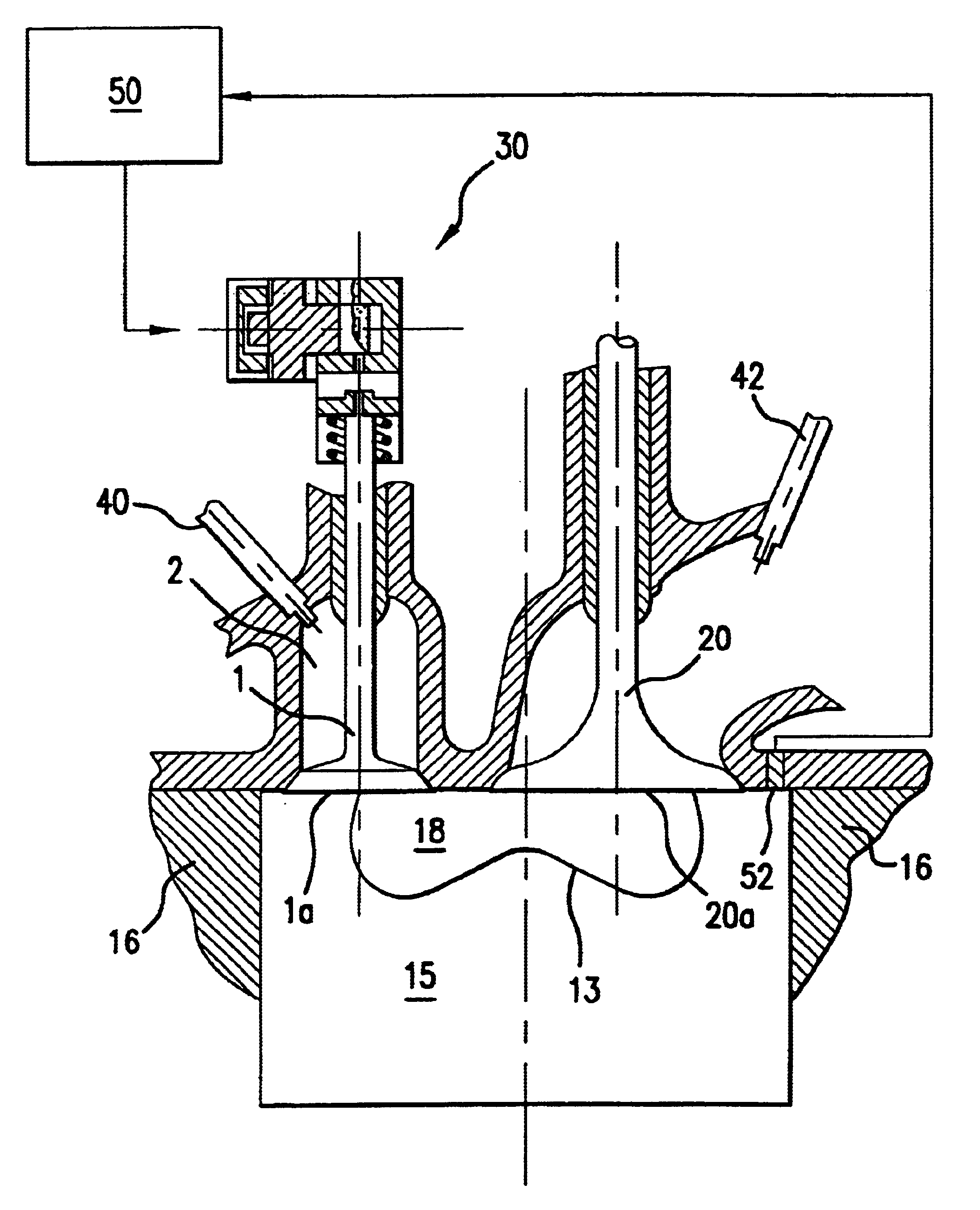
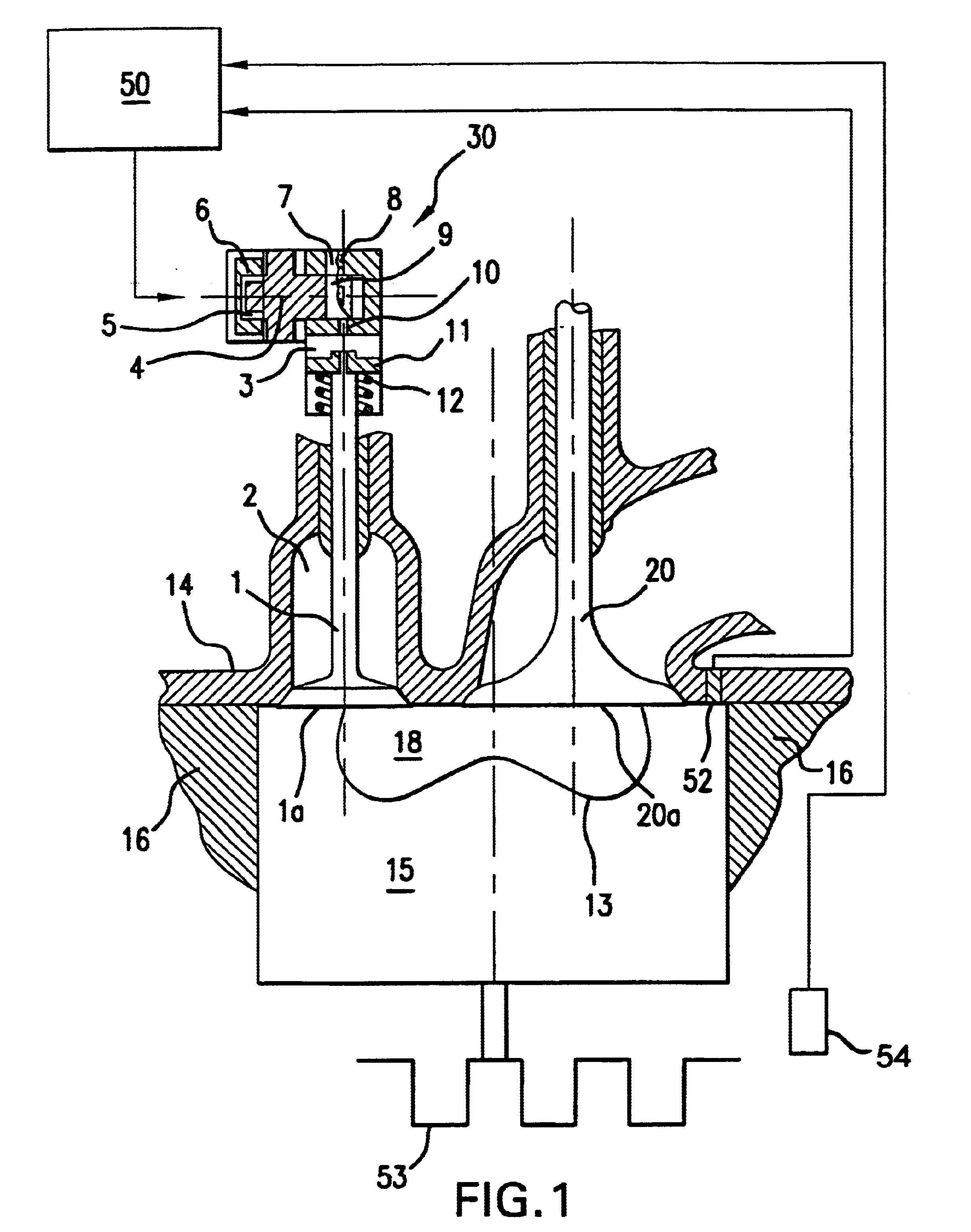
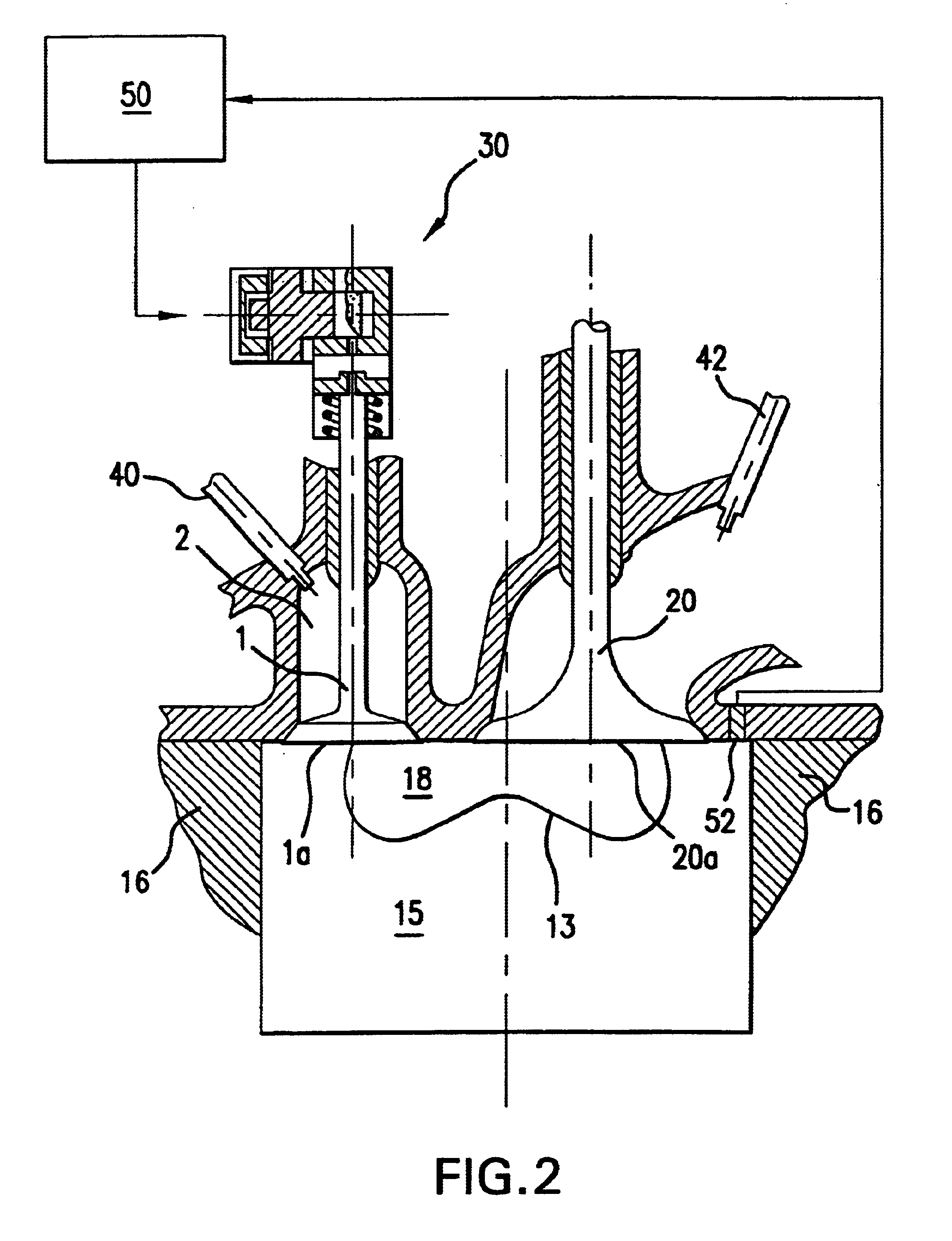
[0022]FIG. 1 shows a first preferred embodiment of the present invention in the form of a reciprocating internal combustion engine which includes a combustion-tailoring chamber (CTC) 2 in the cylinder head 14. Piston 15 is provided with a piston bowl 13 in its face forming the main combustion chamber. The volume of the chamber 2 can be from 5 to 70% of the volume of piston bowl 13. There is a valve 1 between the chamber 2 and the main combustion chamber. The area of the surface 1a of valve 1 is equal to or smaller than that of surface 20a of the intake valve 20. The piston 15 is one of plural pistons drivably connected to an engine crankshaft 53. A sensor 52 monitors combustion chamber pressure and a sensor 54 monitors engine speed and / or crank angle.

[0023]The valve 1 is controlled electro-hydraulically by a control unit 30 responsive to signals from a controller 50. Hydraulic fluid with pressure on the order of 2000 psi is provided to the control unit inlet 7. To open the valve 1, ...


PUM


Abstract

An internal combustion engine is adapted for operation with homogeneous combustion and compression ignition. The engine includes plural cylinders with the piston in each cylinder defining the main combustion chamber and connected to a crankshaft for reciprocating motion rotatably driving the crankshaft. An auxiliary combustion chamber and an inlet passage are formed in the engine head for each of the cylinders with a control valve for controlling communication between the main combustion chamber and the auxiliary combustion chamber and an inlet valve for controlling communication between the main combustion chamber and the inlet passage. The inlet valve is driven with rotation of the crankshaft, while the drive for the combustion control valve is independent of angular position of the crankshaft and has its own controller for timing its opening and closing to provide controlled homogeneous combustion.

Description

BACKGROUND OF THE INVENTION[0001]This invention relates to a method and apparatus for controlling the operation of Homogeneous Charge Compression Ignition (HCCI) engines over a wide range of speeds and loads. HCCI is a type of combustion in which a premixed fuel air mixture is brought to auto-ignition near the end of the compression stroke. Engines using HCCI combustion have the potential to meet future stringent emission standards with increased fuel efficiency and without penalty in production cost. Engines operating with HCCI combustion can be used for passenger cars, buses, trucks as well as non-road and off-road applications.The Prior Art[0002]HCCI has been identified for many years as a distinct combustion phenomenon. When certain conditions are met within a hot homogenous charge, auto-ignition would occur at many different points simultaneously and without flame propagation. Many studies have suggested that the HCCI is controlled by the onset of dissociation of the hydrogen p...

Claims


Application Information

Patent Timeline
IPC IPC(8): F02B19/02F02B19/10F02B1/12F01L9/02F02B1/00F02B19/00F01L9/00F02B23/02F02B23/06F01L9/10
CPCF01L9/02F02B1/12F02B19/02F02B19/108F01L2800/00Y02T10/123F02B23/0696F02B2275/16Y02T10/125Y02T10/128F02B23/0621Y02T10/12F01L9/10
Inventor SUN, RUONANHELLMAN, KARL H.GRAY, CHARLES L.
Owner ENVIRONMENTAL PROTECTION AGENCY US
Learn More