Evaporated fuel processing apparatuses for engines with supercharger

a technology of evaporation fuel and processing apparatus, which is applied in the direction of mechanical apparatus, combustion air/fuel air treatment, machines/engines, etc., can solve the problems of deterioration of exhaust gas, delay in opening and closing the change-over valve, and problems such as the effect of affecting the operation of the change-over valv

Active Publication Date: 2005-06-28
AISAN IND CO LTD
View PDF14 Cites 43 Cited by
  • Summary
  • Abstract
  • Description
  • Claims
  • Application Information

AI Technical Summary

Benefits of technology

[0012]To achieve the purpose of the invention, there is provided an evaporated fuel processing apparatus for an engine with a supercharger, for collecting evaporated fuel generated in a fuel tank into a canister and purging the collected evaporated fuel from the canister to an intake passage of the engine, the supercharger including a compressor provided in the intake passage, the evaporated fuel processing apparatus comprising: a purge passage through which the evaporated fuel is purged from the canister into the intake passage located upstream of the compressor; an electromagnetic valve for opening and closing the purge passage; operating condition detection means which detects an operating condition of the engine; and control means which controls the opening and closing operations of the electromagnetic valve so that the electromagnetic valve is opened when the control means determines that intake pressure of the engine is an atmospheric pressure or more on the basis of the detected operating condition of the engine and the electromagnetic valve is closed when the control means determines that the intake pressure of the engine is less than the atmospheric pressure.
[0013]According to another aspect, the invention provides an evaporated fuel processing apparatus for an engine with a supercharger, for collecting evaporated fuel generated in a fuel tank into a canister and purging the collected evaporated fuel from the canister into an intake passage of the engine, the supercharger including a compressor provided in the intake passage, the evaporated fuel processing apparatus comprising: a first purge passage through which the evaporated fuel is purged from the canister into the intake passage located upstream of the compressor; a first electromagnetic valve for opening and closing the first purge passage; operating condition detection means which detects an operating condition of the engine; a throttle valve provided in the intake passage located downstream of the compressor; a second purge passage through which the evaporated fuel is purged from the canister into the intake passage located downstream of the throttle valve; a second electromagnetic valve for opening and closing the second purge passage; and control means which controls the opening and closing operations of the first and second electromagnetic valves so that the second electromagnetic valve is closed when the control means determines that intake pressure of the engine is an atmospheric pressure or more on the basis of the detected operating condition of the engine and then the first electromagnetic valve is opened, and the first and second electromagnetic valves are closed when the control means determines that the intake pressure of the engine is less than the atmospheric pressure.
[0014]According to another aspect, the invention provides an evaporated fuel processing apparatus for an engine with a supercharger, for collecting evaporated fuel generated in a fuel tank into a canister and purging the collected evaporated fuel from the canister to an intake passage of the engine, the supercharger including a compressor provided in the intake passage, the evaporated fuel processing apparatus comprising: a purge passage through which the evaporated fuel is purged from the canister into the intake passage located upstream of the compressor; a supercharging pressure passage through which a supercharging pressure in the intake passage downstream of the compressor is supplied to the canister as a back pressure; an electromagnetic valve for opening and closing the purge passage; operating condition detection means for detecting an operating condition of the engine; and control means which controls the opening and closing operations of the electromagnetic valve on the basis of the detected operating condition of the engine.
[0015]According to another aspect, the invention provides an evaporated fuel processing apparatus for an engine with a supercharger, for collecting evaporated fuel generated in a fuel tank into a canister and purging the collected evaporated fuel from the canister into an intake passage of the engine, the supercharger including a compressor provided in the intake passage, the evaporated fuel processing apparatus comprising: a purge passage through which the evaporated fuel is purged from the canister into the intake passage located upstream of the compressor; an aspirator, provided in the purge passage, for drawing in the evaporated fuel flowing through the purge passage by allowing working gas to flow; a supercharged air passage through which supercharged air in the intake passage downstream of the compressor is allowed to flow in the aspirator as the working gas; an electromagnetic valve for opening and closing the purge passage; operating condition detection means which detects an operating condition of the engine; and control means for controlling the opening and closing operations of the electromagnetic valve on the basis of the detected operating condition of the engine.
[0016]According to another aspect, the invention provides an evaporated fuel processing apparatus for an engine with a supercharger, for collecting evaporated fuel generated in a fuel tank into a canister and purging the collected evaporated fuel from the canister to an intake passage of the engine, the supercharger including a compressor provided in the intake passage, the evaporated fuel processing apparatus comprising: a purge passage through which the evaporated fuel is purged from the canister into the intake passage located downstream of the compressor; an aspirator, provided in the purge passage, for drawing in the evaporated fuel flowing through the purge passage by allowing working gas to flow; a supercharged air passage through which supercharged air in the intake passage downstream of the compressor is allowed to flow in the aspirator as the working gas; an electromagnetic valve for opening and closing the purge passage; operating condition detection means which detects an operating condition of the engine; and control means which controls the opening and closing operations of the electromagnetic valve on the basis of the detected operating condition of the engine.

Problems solved by technology

In the apparatus of the document 1, however, since the change-over valve is a diaphragm type valve, a response delay in opening and closing the change-over valve would become problems as below.
However, there may be cases where a supercharger operates by inertia even just after deceleration, causing a delay in opening the change-over valve.
The evaporated fuel at this time would not burn or incompletely burn in a combustion chamber, which results in a deterioration in exhaust gas.
Consequently, the check valve tends to close later during deceleration of the engine and the evaporated fuel also may be caused to flow in the intake passage.
Accordingly, when the supercharger operates by inertia just after deceleration of the engine, the evaporated fuel is also caused to flow in the intake passage, leading to a deterioration in exhaust gas.
This also may cause the evaporated fuel to flow in the intake passage.

Method used


Image

  • Evaporated fuel processing apparatuses for engines with supercharger
  • Evaporated fuel processing apparatuses for engines with supercharger
  • Evaporated fuel processing apparatuses for engines with supercharger

Examples


first embodiment

[0027][First Embodiment]

[0028]A detailed description of a first preferred embodiment of an evaporated fuel processing apparatus for an engine with a supercharger embodying the present invention will now be given referring to the accompanying drawings.

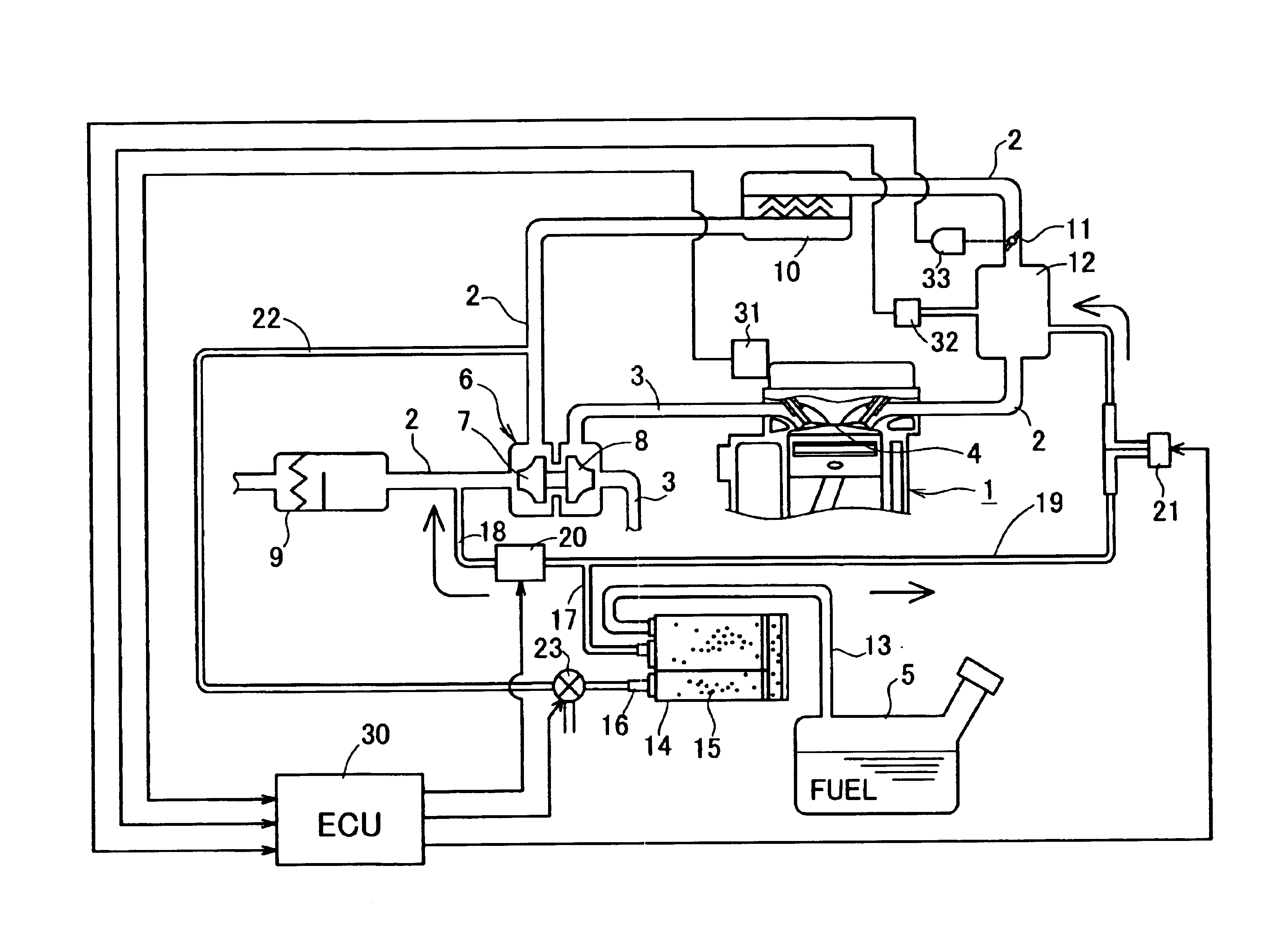
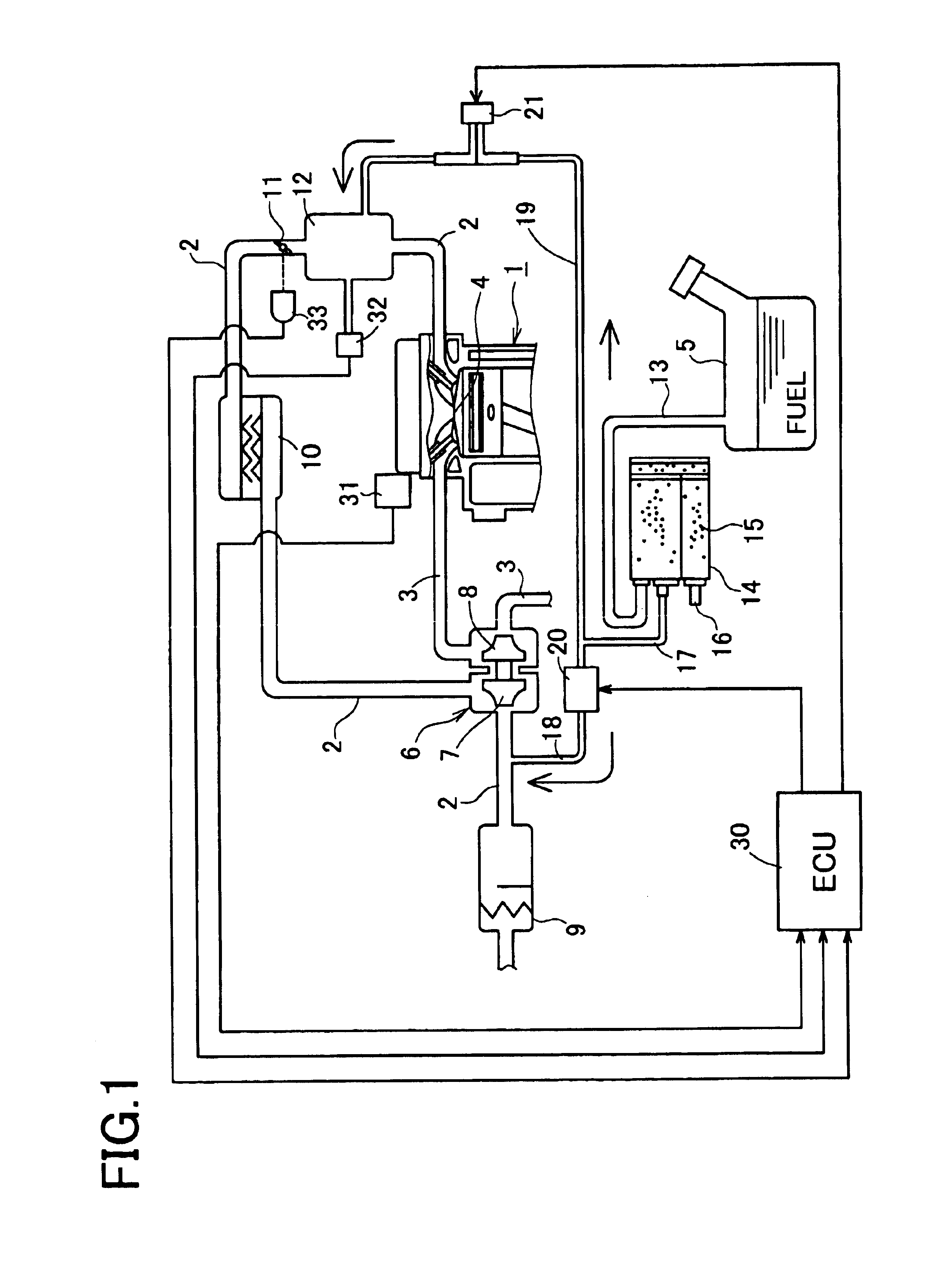
[0029]FIG. 1 is a schematic perspective view of an engine system with a supercharger in the present embodiment. An engine 1 is provided with an intake passage 2 for taking in outside air and an exhaust passage 3 for discharging exhaust gas. Fuel stored in a fuel tank 5 is supplied for combustion to a combustion chamber 4 of the engine 1 by a predetermined fuel supply device (not shown).

[0030]A turbocharger 6 serving as a supercharger is provided at a position of the intake passage 2 and the exhaust passage 3. More specifically, a compressor 7 constituting the turbocharger 6 is disposed in the intake passage 2 and a turbine 8 also constituting the turbocharger 6 is disposed in the exhaust passage 3. As it is generally known, the turbocha...

second embodiment

[0058][Second Embodiment]

[0059]Next, a second preferred embodiment of the evaporated fuel processing apparatus for an engine with a supercharger will be described with reference to attached drawings.

[0060]It is to be noted that in the second and subsequent embodiments, like elements corresponding to those in the first embodiment are indicated by like numerals and their explanations are omitted. The following embodiments will be explained with a focus on different structures from those in the first embodiment.

[0061]FIG. 3 is a schematic perspective view of an engine system with a supercharger in the second embodiment. The evaporated fuel processing apparatus in this embodiment differs from that in the first embodiment in that the apparatus in the second embodiment further includes a supercharging pressure passage 22 through which a supercharging pressure in the intake passage 2 downstream of the compressor 7 is supplied as a back pressure to the canister 14 and a third electromagneti...

third embodiment

[0069][Third Embodiment]

[0070]Next, a third preferred embodiment of the evaporated fuel processing apparatus for an engine with a supercharger will be described with reference to attached drawings.

[0071]FIG. 5 is a schematic perspective view of an engine system with a supercharger in the present embodiment, which differs from that in the first embodiment in that the system in the third embodiment includes an aspirator 24 which allows working gas to flow to thereby draw in the vapor flowing through the first purge line 18, and a passage 25 for supplying supercharged air from the intake passage 2 downstream of the compressor 7 to the aspirator 24 as the working gas.

[0072]Specifically, one end (i.e., an upstream end) of the supercharged air passage 25 is connected in communication with the intake passage 2 downstream of the compressor 7 and the other end (i.e., a downstream end) is connected in communication with the aspirator 24. The aspirator 24 is adapted to allow the supercharged a...


PUM


Abstract

In an engine with a supercharger, there is provided an evaporated fuel processing apparatus for collecting vapor generated in a fuel tank into a canister and purging the collected vapor into an intake passage. The supercharger includes a compressor. The evaporated fuel processing apparatus comprises a purge passage through which the vapor is purged from the canister into the intake passage upstream of the compressor, a second purge passage through which the vapor is purged from the canister into a surge tank, two electromagnetic valves which are operated to open and close the two purge passage, various sensors which detect an operating condition of the engine, and an electronic control unit (ECU) which controls the electromagnetic valves respectively on the basis of values detected by the sensors.

Description

BACKGROUND OF THE INVENTION[0001]1. Field of the Invention[0002]The present invention relates to an evaporated fuel processing apparatus adapted to collect evaporated fuel generated in a fuel tank into a canister and then purge the collected evaporated fuel into an intake passage of an engine and, more particularly, to an evaporated fuel processing apparatus provided for an engine with a supercharger.[0003]2. Description of Related Art[0004]Some conventional arts related to an evaporated fuel processing apparatus for an engine with a supercharger are disclosed in for example the following patent documents; Patent document 1 (Japanese patent unexamined publication No. Sho 62-18747, particularly, pages 1-2 and FIG. 2), Patent document 2 (Japanese patent publication No. Sho 59-563, particularly, pages 1-3 and FIG. 2), and Patent document 3 (Japanese patent publication No. Hei 5-10216, particularly, pages 2-7 and FIGS. 1 and 5).[0005]Patent Document 1 discloses an apparatus constructed ...

Claims


Application Information

Patent Timeline
Patent Type & Authority Patents(United States)
IPC IPC(8): F02M25/08F02B37/00F02D23/00
CPCF02M25/08F02B37/00
Inventor MURAKAMI, KENICHINAGAI, TAKASHIWADA, SATOMI
Owner AISAN IND CO LTD
Why Eureka
Try Eureka