Torsional-vibration damper

Active Publication Date: 2005-06-28
BORG WARNER INC
View PDF57 Cites 12 Cited by
  • Summary
  • Abstract
  • Description
  • Claims
  • Application Information

AI Technical Summary

Benefits of technology

[0012]Another advantage of the torsional-vibration damper of the present invention is that the control system can be produced cost-effectively.
[0013]Another advantage of the torsional-vibration damper of the present invention is that variability of the damping effect of the frictional contact is achieved.
[0014]Another advantage of the torsional-vibration damper of the present invention is that the control system for controlling and adjusting the frictional engagement of the two eleme

Problems solved by technology

When torsional-vibration dampers are used in the drive train, however, it is necessary to have a high moment of friction in the drive train to decrease the vibration amplitudes in the resonance range.
Unfortunately, this causes the transmission characteristic to deteriorate in higher speed range.
Although the torsional-vibration damper disclosed in the

Method used


Image

  • Torsional-vibration damper
  • Torsional-vibration damper
  • Torsional-vibration damper

Examples


first embodiment

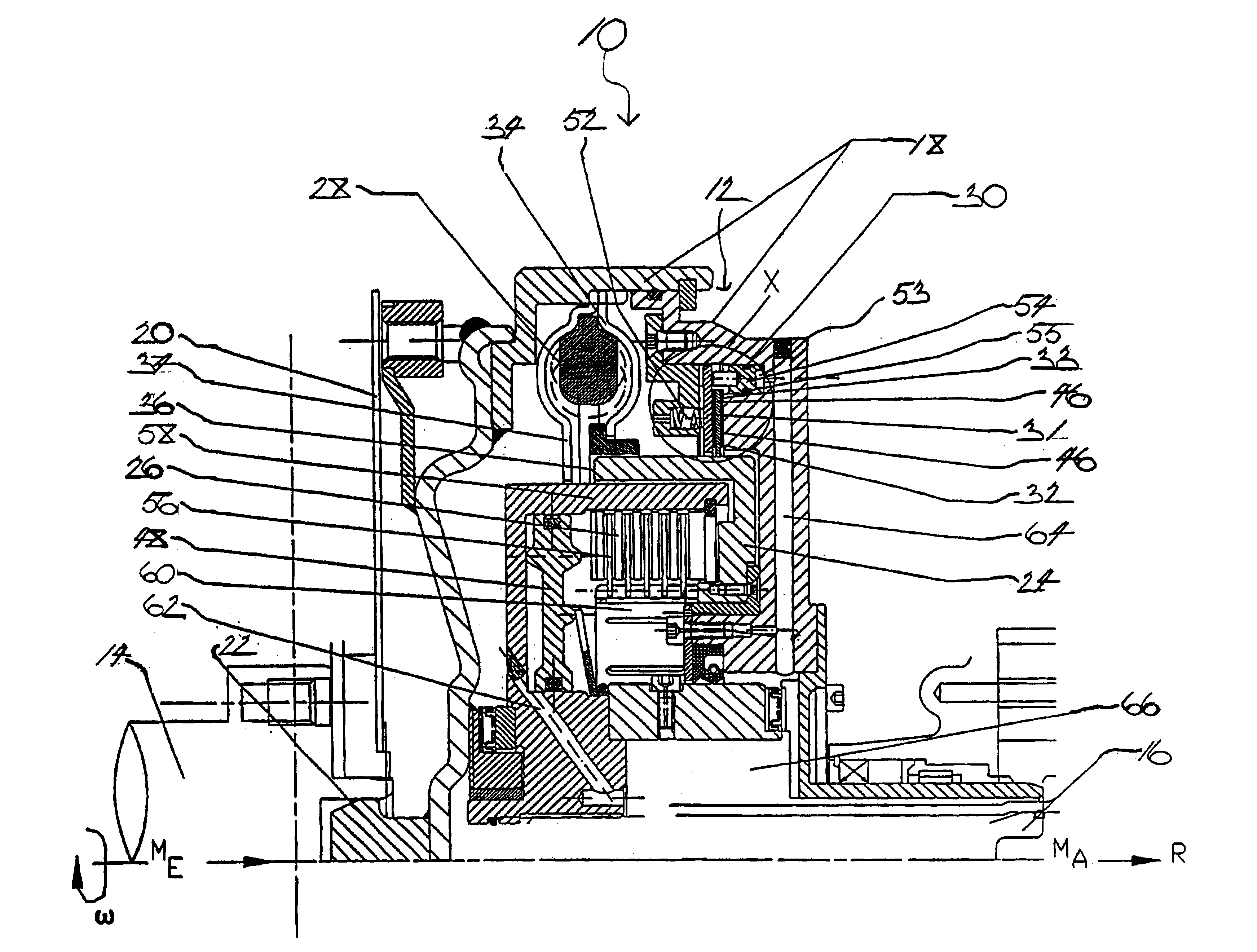
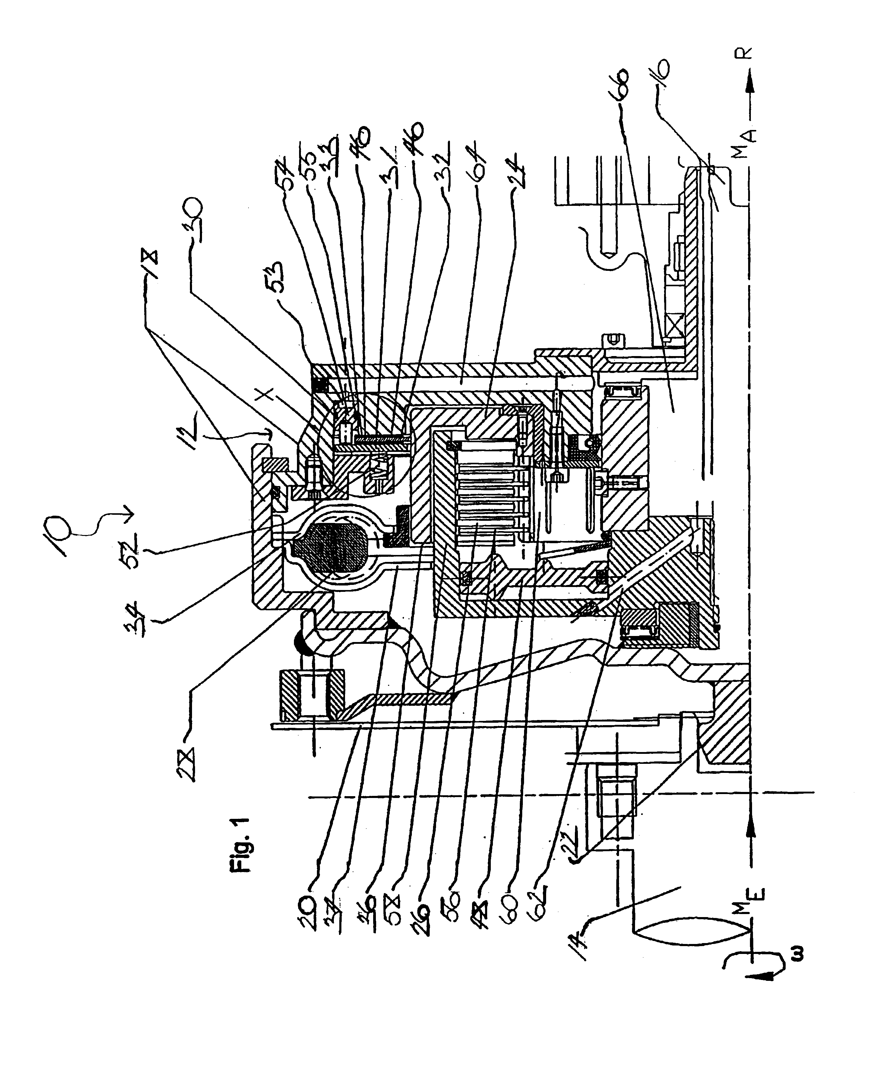
[0028]Referring now to FIGS. 1 through 4b, where like numerals are used to designate like structure, a section of a first exemplary drivetrain of a motor vehicle is generally indicated at 10 in FIG. 1 and illustrates a possible basic structure and functional method of the torsional-vibration damper of the present invention, generally indicated at 12. In general, a flange 14—coupled to, for example, an internal-combustion engine, a motor, or the like—represents the driving side of the drive train 10. A shaft 16—coupled to, for example, a transmission (not shown) or the like—represents the power-take-off side of the drive train 10. The torsional-vibration damper 12 is disposed between the driving side and the power-take-off side and, thus, the flange 14 and the shaft 16. Consequently, a torque “ME” introduced on the driving side by rotational speed “ω” via the flange 14 can be transmitted via the torsional-vibration damper 12 to the shaft 16 and, thus, to the power-take-off side. The ...

second embodiment

[0051]Referring now to FIG. 5, where like numerals increased by 100 are used to designate structure like that of FIGS. 1-3b, a section of a second exemplary drivetrain of a motor vehicle is generally indicated at 110 and illustrates a possible basic structure and functional method of a torsional-vibration damper of the present invention, generally indicated at 112. In general, a flange 114 represents the driving side of the drive train 110 and is operatively coupled to, for example, an internal-combustion engine, a motor, or the like. A shaft 116 represents the power-take-off side of the drive train 110 and is operatively coupled to, for example, a transmission (not shown) or the like. The torsional-vibration damper 112 is disposed between the driving side and the power-take-off side and, thus, the flange 114 and the shaft 116. Consequently, a torque “ME” introduced on the driving side by rotational speed “ω” via the flange 114 can be transmitted via the torsional-vibration damper 1...

third embodiment

[0066]the torsional-vibration damper 212 generally includes at least one primary element 218 and a secondary element 224. A spring device, generally indicated at 228, is adapted to couple the at least one primary element 218 and the secondary element 224 to each other. The at least one primary element 218 and the secondary element 224 are limited in movement in relation to each other about a rotational axis indicated by the reference “R.” A friction device, generally indicated at 230, is adapted to bring the at least one primary element 218 and the secondary element 224 into frictional contact with each other and includes at least two friction-surface-carrying elements 231, 232, 233 rubbing against each other. A force-generating device, generally indicated at 251, is adapted to generate a contact-pressure force to be applied to the at least two elements 231, 232, 233 to produce a frictional engagement therebetween. The force-generating device 251 includes a mechanical actuating mech...


PUM


Abstract

A torsional-vibration damper includes at least one primary element and a secondary element that can be coupled to each other by a spring device, are limited in movement in relation to each other about a rotational axis, and can be brought into frictional contact with each other by a friction device. The friction device has at least two friction-surface-carrying elements rubbing against each other to which a contact-pressure force, generated by a force-generating device, can be applied to produce a frictional engagement between the two elements. The force-generating device has a mechanical actuating mechanism for generating an actuating force and a hydraulic actuating mechanism for generating a counterforce, wherein the contact-pressure force is a vector sum of the actuating force and the counterforce.

Description

BACKGROUND OF THE INVENTION[0001]1. Field of the Invention[0002]The present invention relates, generally, to a motor vehicle and, particularly, to a torsional-vibration damper of the vehicle.[0003]2. Description of the Related Art[0004]A torsional-vibration damper is, generally, a type of elastic coupling disposed between two components of a drive train of a vehicle, for example, between an internal-combustion engine and a transmission. Such devices prevent vibrations from being transmitted from the engine to other parts of the drive train.[0005]The basic embodiment of a torsional-vibration damper includes a primary element and a secondary element that can be coupled to each other by a spring device and are limited in movement in relation to each other about a rotational axis. The spring device advantageously includes a plurality of springs disposed on a radial arc spaced relative to the rotational axis and, preferably, at a certain uniform distance from each other. The springs, or ...

Claims


Application Information

Patent Timeline
IPC IPC(8): F16D25/06F16F15/139F16D25/0635F16F15/131F16D48/00F16D48/02F16D25/0638F16F15/134
CPCF16D25/0635F16D25/14F16F15/139F16D48/02F16F2230/183F16D2300/14F16D2500/1045F16D2500/50293
Inventor BAUER, KARL-HEINZSCHAFER, MICHAELHAUCK, HANS JURGENHEINRICH, JOHANNES
Owner BORG WARNER INC
Why Eureka
Try Eureka