Container valve

a container valve and valve body technology, applied in the direction of container discharging methods, liquid handling, packaged goods types, etc., can solve the problems of difficult to maintain safety, inflammability, spontaneous inflammability, toxic, corrosive and combustible supportability, etc., and achieve the effect of safe gas supply

Inactive Publication Date: 2005-06-28
HAMAI INDS +1
View PDF3 Cites 32 Cited by
  • Summary
  • Abstract
  • Description
  • Claims
  • Application Information

AI Technical Summary

Benefits of technology

[0009]Here, an objective of this invention is to provide a container valve that can safely supply gas under reduced pressure when opening the container valve wherein the pressure inside the container remains high.

Problems solved by technology

Gas used in industry (industrial gas) is often high-pressure gas having dangerous characteristics such as being inflammable, spontaneous-flammable, and toxic, corrosive and combustible-supportability.
This makes it difficult to maintain safety.
Especially in the semiconductor industry, the larger the diameter of a wafer is, the more semiconductor gas with dangerous characteristics consumed.
There are two drawbacks: high danger with gas leakage due to the existence of the high-pressure portion and high cost due to using the authorized parts.
Although the technique has great merit in terms of filling amount, it also has the problem that the gas cannot be supplied unless the pressure of consumption equipment is 10 or less than 10 Torr.
This technique can only be used in the semiconductor industry using ion implantation or high-density plasma CVD etc.
Furthermore, because the absorbent is used, it is difficult to remove the atmospheric impurity absorbed by the adsorbent.
Additionally, because the adsorbent is also the source for generating particles, high purity gas cannot be provided.
Since this container is not functional to efficiently fill the container with gas, because it is difficult to exhaust the container into a vacuum state before filling the gas and the filling speed is slow.
As a result, the filled gas is of low purity.
Furthermore, the remaining amount of gas cannot be managed with the low-pressure inside the container.

Method used


Image

  • Container valve
  • Container valve
  • Container valve

Examples


first embodiment

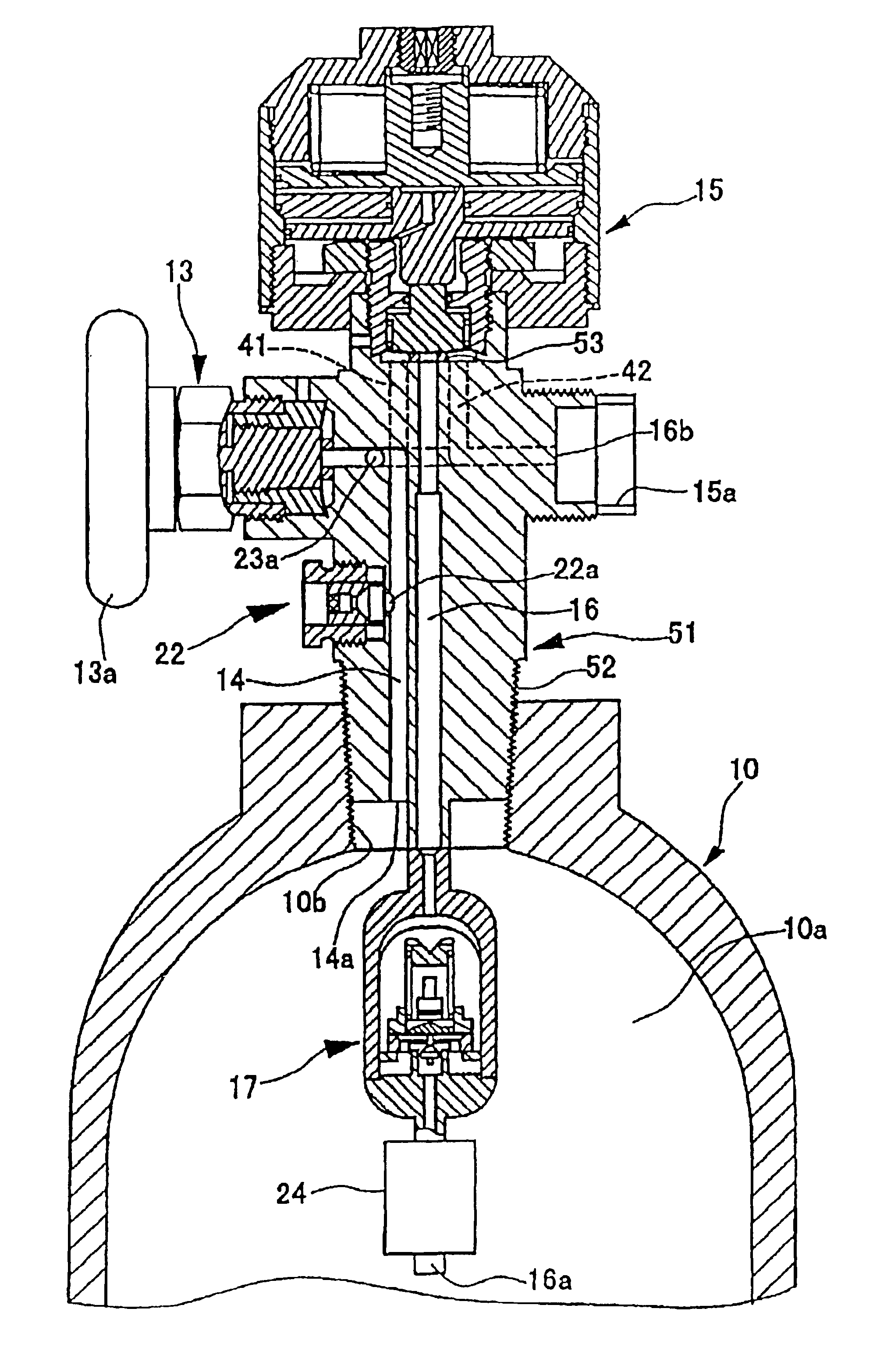
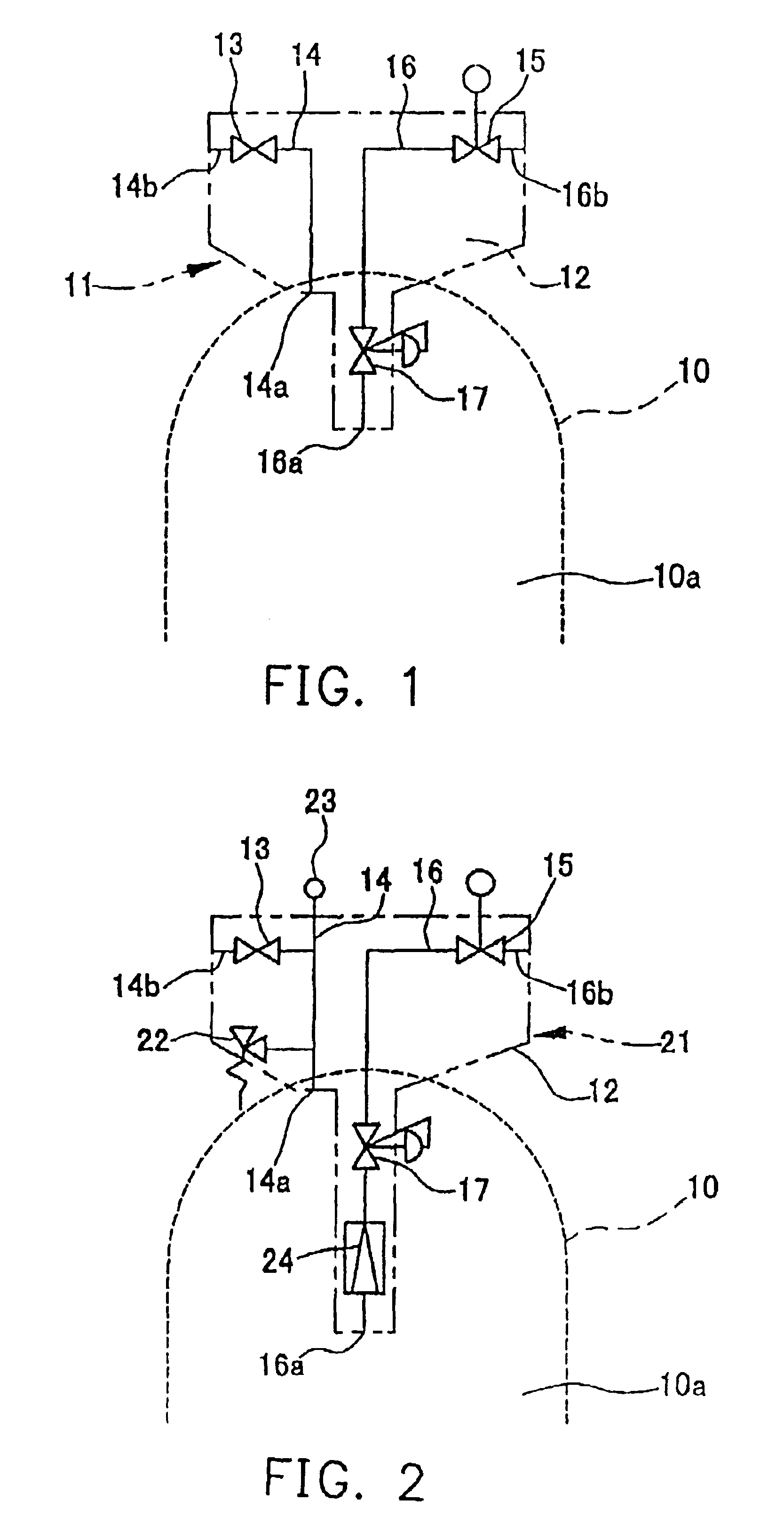
[0028]FIG. 1 is a system diagram of the container valve with pressure reducing function according to the present invention. The container valve 11 with pressure reducing function attached to a gas container 10 comprises a gas filling passage 14 in which a stop valve (filling valve) 13 is installed, a gas lead-out passage 16 in which a stop valve (lead-out valve) 15 is installed and a regulator 17. The gas filling passage 14 and the gas lead-out passage 16 are set inside a valve block 12 installed onto the gas container 10. The pressure regulator 17 is set on the upstream side (front section) of the lead-out valve 15 in the gas lead-out passage 16. The gas filling passage 14 communicates with the gas phase 10a inside the container through a gas filling outlet 14a. A filling gas inlet 14b and the gas phase 10a are separated by the filling valve 13 Moreover, the gas lead-out passage 16 communicates with the gas phase 10a inside the container through a gas lead-out inlet 16a. A gas lead...

second embodiment

[0031]FIG. 2 is a system diagram showing a container valve with pressure reducing function according to the present invention. In the following description, for the same elements in the container valve with pressure reducing function mentioned in each embodiment with the same numerical references the explanation thereof is omitted.

[0032]In the container valve 21 with pressure reducing function as shown in this embodiment, a safety relief valve 22 is connected between the downstream side (rear section) of the filling valve 13 in the gas filling passage 14 and the gas filling outlet 14a.

[0033]The container valve 21 integrated with the safety relief valve 22 also can be installed onto the gas container that has only one location for container valve installation.

[0034]Additionally, in the container valve 21 with pressure reducing function shown in this embodiment, a pressure sensor 23 is also connected to the downstream side of the filling valve 13 in the gas filling passage 14. The pr...

third embodiment

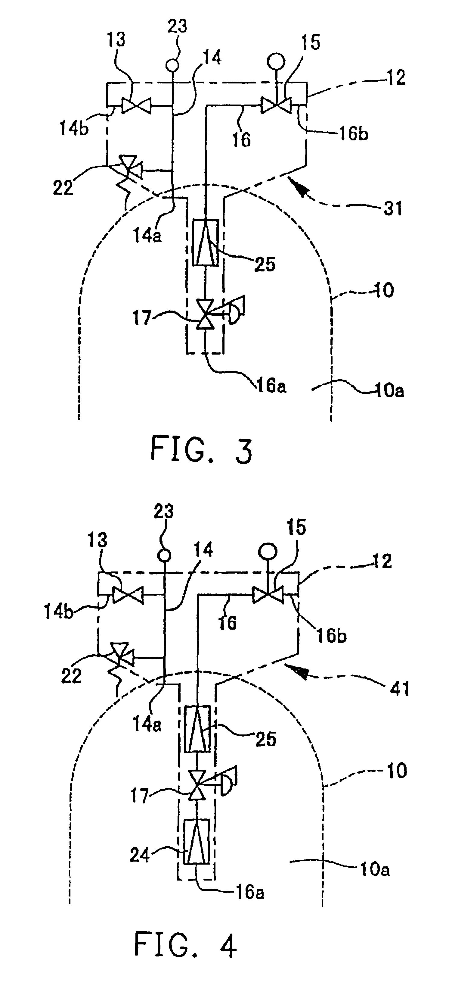
[0037]FIG. 3 is a system diagram showing a container valve with pressure reducing function according to the present invention. In the container valve 31 with pressure reducing function as shown in this embodiment, the filter 25 is assembled onto the downstream side of the pressure regulator 17 in the gas lead-out passage 16 and the upstream side of the lead-out valve 15. By setting the filter 25 onto this position, the particle inside the gas supplied to objects for consumption through the gas lead-out passage 16 can be removed.


PUM

PropertyMeasurementUnit
pressureaaaaaaaaaa
lengthaaaaaaaaaa
lengthaaaaaaaaaa

Abstract

A container valve, attached to a gas container, wherein the container valve has a pressure reducing function, and is inside a valve block in the gas container. In the valve block, the container valve comprises a gas filling passage in which a filling valve is installed, a gas lead-out passage in which a lead-out valve is installed, and a pressure regulator arranged at an upstream side of the lead-out valve in the gas lead-out passage. The container valve can safely supply gas under a reduced pressure for use by opening the container valve of a container whose pressure is high and gas can be filled easily into the container. The container valve can be miniaturized and the purging operation for supplying high purity gas can be performed.

Description

CROSS-REFERENCE TO RELATED APPLICATION[0001]This application claims the priority benefit of Japanese application serial No. 2001-367045, filed on Nov. 30, 2001.BACKGROUND OF THE INVENTION[0002]1. Field of the Invention[0003]This invention relates in general to a container valve with pressure reducing function, and more specifically relates to a valve with a structure suitable for a gas container filled with various gases that have the characteristics of being inflammable, spontaneous-flammable, and toxic, corrosive and combustible-supportability.[0004]2. Description of Related Art[0005]Gas used in industry (industrial gas) is often high-pressure gas having dangerous characteristics such as being inflammable, spontaneous-flammable, and toxic, corrosive and combustible-supportability. The gas is supplied to and consumed by consumption equipment. This makes it difficult to maintain safety. Especially in the semiconductor industry, the larger the diameter of a wafer is, the more semicon...

Claims


Application Information

Patent Timeline
Patent Type & Authority Patents(United States)
IPC IPC(8): F17C13/04
CPCF17C13/04F17C2265/012F17C2205/0391F17C2227/044F17C2270/0518Y02E60/321F17C2201/0109F17C2205/0329F17C2205/0332F17C2205/0335F17C2205/0385F17C2221/03F17C2221/05F17C2223/0123F17C2223/035F17C2250/043F17C2250/0626F17C2205/0338Y02E60/32
Inventor HASAKA, SATOSHIHORIUCHI, YUTAKAKOIZUMI, MASAO
Owner HAMAI INDS
Why Eureka
Try Eureka