Fixing element and ancillary for stabilizing vertebrae

a fixing element and ancillary technology, applied in the field of spinal osteosynthesis, can solve the problems of fastidious and delicate operation of the adjustment of the screwing degree of each of the blocking screws, and achieve the effect of preserving the degree of correction and minimizing friction

Inactive Publication Date: 2005-06-28
SPINEVISION +1
View PDF7 Cites 96 Cited by
  • Summary
  • Abstract
  • Description
  • Claims
  • Application Information

AI Technical Summary

Benefits of technology

[0012]The aim of the invention is to avoid these inconveniences by proposing a system and an implant making it possible to preserve the degree of correction decided by the surgeon during the operations of definitive fixatio

Problems solved by technology

The problem of devices of prior art is that of maintenance of the orientation decided by the surgeon at the time of the definitive fixation and of the dissociation between the positioning of the linkage element and the insertion of the bone implant.
Another

Method used


Image

  • Fixing element and ancillary for stabilizing vertebrae
  • Fixing element and ancillary for stabilizing vertebrae
  • Fixing element and ancillary for stabilizing vertebrae

Examples


Embodiment Construction

)

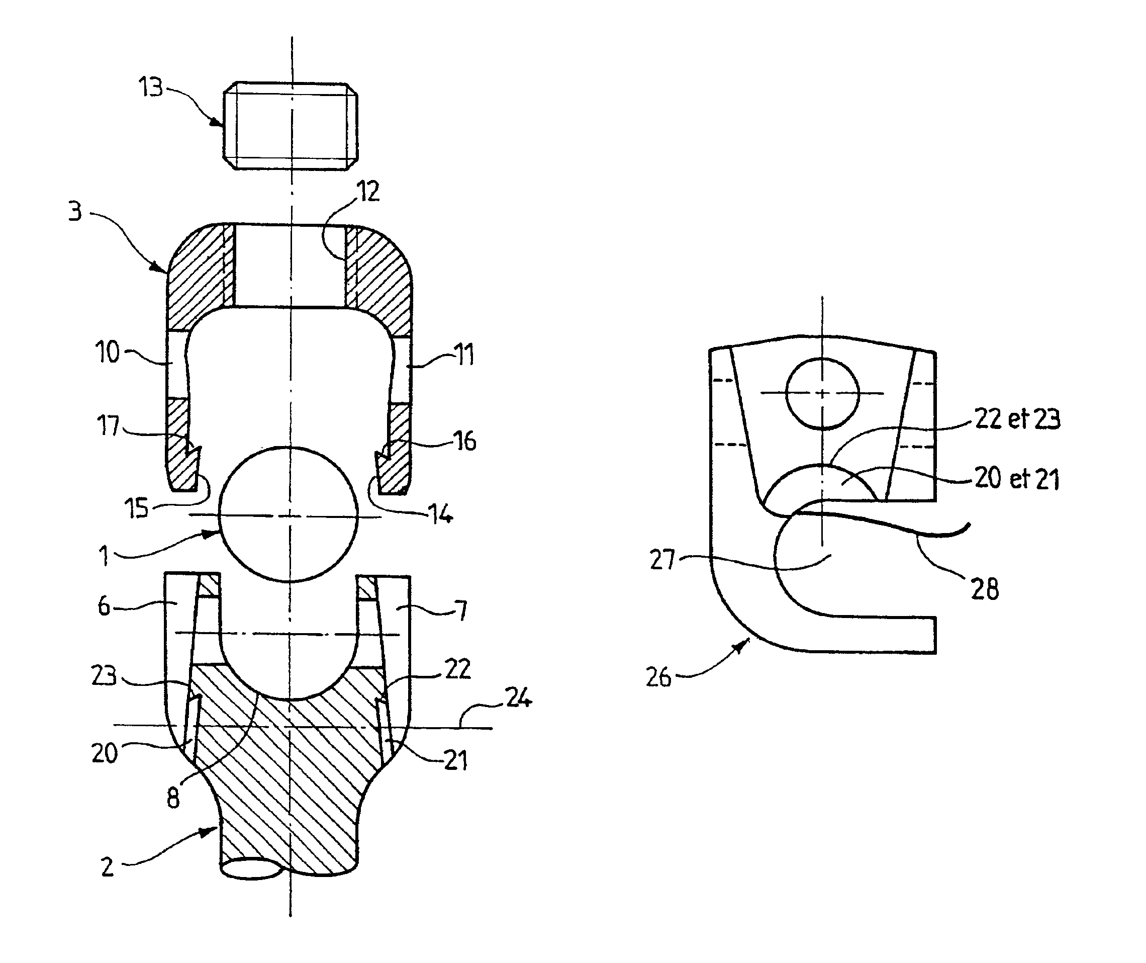
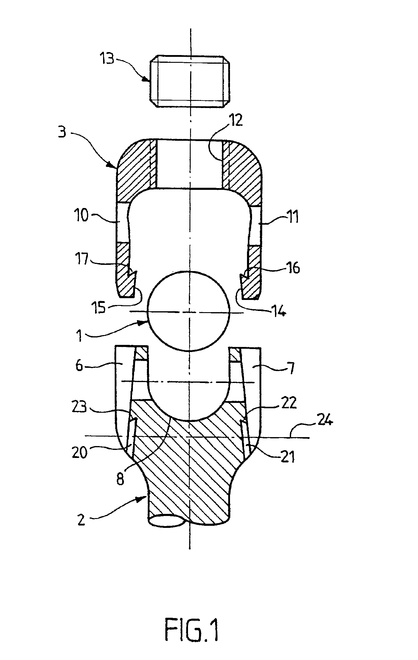
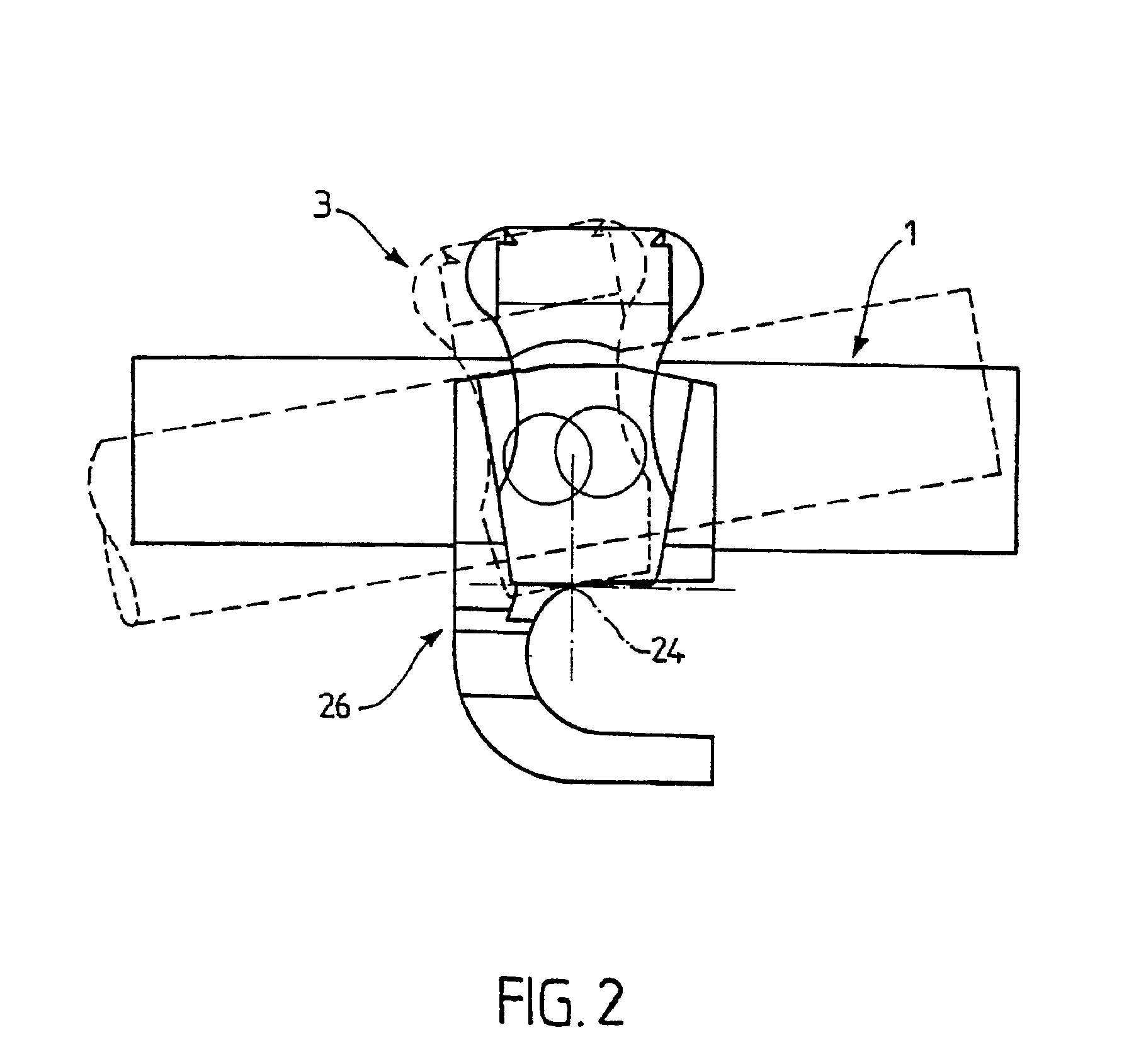
[0031]The osteosynthesis system according to the present invention comprises a linkage element (1), an implant (2) with a complementary closure part (3), and a blocking screw (13).

[0032]The rod (1) will not be described in greater detail since it belongs to the present state of the art and can take diverse forms. In the example given, it is formed of a metallic rod with a circular cross-section.

[0033]The implant has a fork shaped head (5), with two lateral arms (6, 7) defining a space intended to receive the linkage element (1).

[0034]The bottom (8) of the fork is generally horse-shoe shaped, with a concave curve in the transversal plane corresponding to the plane of FIG. 1, and a convex curve in the complementary plane.

[0035]The radius of the concave curve corresponds closely to the external radius of the guiding element (1). The latter thus comes into contact following a semi-peripheral line. This contact according to a line and not according to an annular surface allows a degree ...


PUM


Abstract

The invention concerns an osteosynthesis system, comprising at least a linking element in the form of a rod, at least two fixing elements each capable of being anchored in a vertebra, and a locking screw. The invention is characterized in that the base of the head has a general horse-saddle shape, and the head has guide means for an independent closure component designed to be fixed on the head after the linking element has been positioned in the fork of the head, said closure component being generally U-shaped whereof the branches are urged to co-operate with the branches of-the fork-shaped part of the head and whereof the base comprises an internal thread for co-operating with the locking screw and the guide means provided on the head is formed by an arc-shaped shoulder on the outer side surfaces of the fork-shaped part. The invention also concerns an ancillary and an element for fixing such a system.

Description

BACKGROUND OF THE INVENTION[0001]The present invention relates to the domain of spinal osteosynthesis intended for surgery of the vertebral column, to correct malformations of the degenerative or idiopathic, neuromuscular or tumoral, or of the traumatological type.[0002]In prior art, it is known how to use an instrumentation comprising implants to be fixed on the bone, by screwing or by hooks and linkage elements enabling the surgeon to apply constraints for straightening or stabilising the vertebral column.[0003]As an example, the European patent EP626828 describes such a system enabling osteosynthesis on the vertebral column, together with a linkage element between this system and the tools used for assembly and / or disassembly. This prior art document describes a device for osteosynthesis on the vertebral column, in particular for stabilising the vertebrae, comprising:[0004]at least one linkage element in the shape of a rod.[0005]at least two fixation elements each able to be anch...

Claims


Application Information

Patent Timeline
IPC IPC(8): A61B17/70A61B17/88A61B17/58A61F2/44
CPCA61B17/7032A61B17/7088
Inventor VANACKER, GERARDZELLER, REINHARD
Owner SPINEVISION
Why Eureka
Try Eureka