Method for controlling residual stress in prosthetics

a residual stress and prosthetic technology, applied in the field of producing prosthetics, can solve the problems of large morse taper, inability to provide full or natural range of motion, and inability to fit into smaller bones, and achieve the effect of increasing the strength of smaller prosthetic devices and enhancing the strength of parts

Inactive Publication Date: 2005-06-28
BIOMET MFG CORP
View PDF28 Cites 42 Cited by
  • Summary
  • Abstract
  • Description
  • Claims
  • Application Information

AI Technical Summary

Benefits of technology

[0011]A method for producing predetermined internal stresses in a prosthetic device for implantation. The method includes first determining internal stresses which are preferred in prosthetics to instill a particular strength and longevity to the prosthetic. In particular, internal stresses may be used to increase the strength of smaller prosthetic devices. Additionally, once the preferred internal stresses are determined, the internal stresses can be cold worked into subsequent prosthetic devices to instill the same characteristics. Producing prosthetic devices, including predetermined internal stresses through work hardening the prosthetic devices, is described.

Problems solved by technology

Due to this, the Morse taper is often larger and does not provide a full or natural range of motion.
If the taper is for internal bone connection, a strong enough connection may produce a taper that is too big to fit into smaller bones.
These new metal alloys, however, are still required to have large enough interconnection portions to provide the necessary strength to the materials.
These methods, however, include a certain amount of uncertainty introduced into the prosthetic device.
Therefore, excessive or unnecessary work hardening may be performed or the prosthetic may not be work hardened enough, requiring an earlier replacement than necessary.
In addition, other precautions, such as larger prosthetics, may unnecessarily be used to ensure proper strength.
Furthermore, compressive stresses inhibit the initiation of a crack within the area which is loaded by external forces.
In particular compressive stress near the surface can decrease fatigue and stress corrosion failures.

Method used


Image

  • Method for controlling residual stress in prosthetics
  • Method for controlling residual stress in prosthetics
  • Method for controlling residual stress in prosthetics

Examples


Embodiment Construction

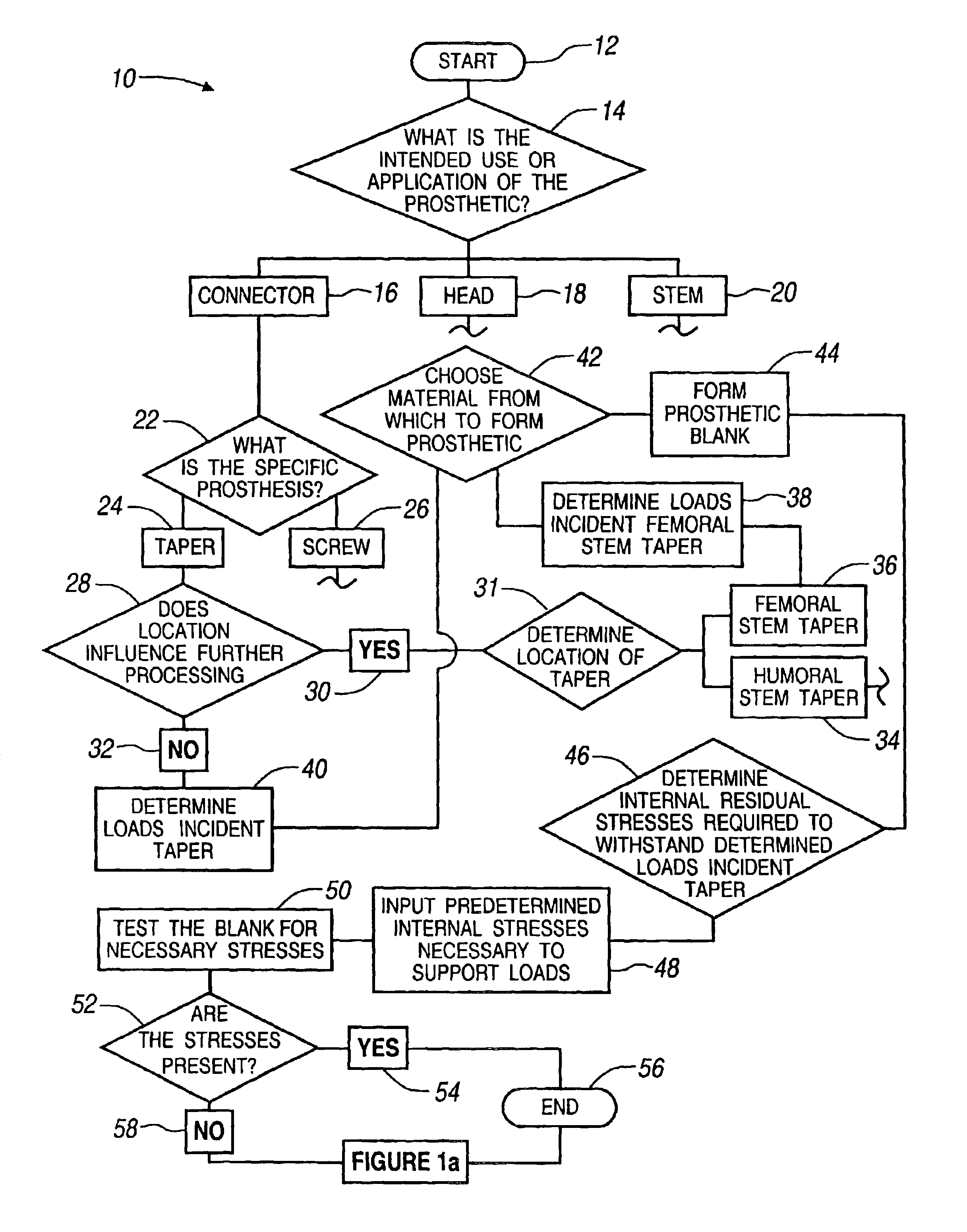
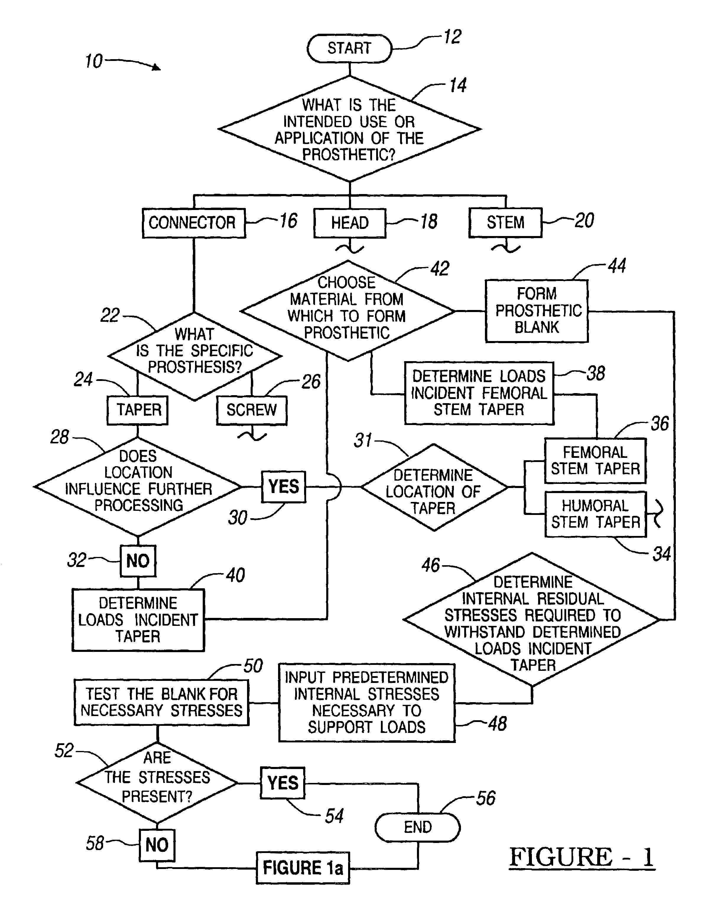
[0024]The following description of the preferred embodiment(s) is merely exemplary in nature and is in no way intended to limit the invention, its application, or uses. Although the following description relates primarily to a Morse taper, it will be understood that the disclosed invention may relate to any portion of any prosthetic device requiring a certain internal residual stress, including other connection portions, bearing surfaces, etc.

[0025]With reference to FIG. 1, a prosthesis device production process 10 is illustrated in a flow chart. The process 10 may be used to produce any number of prosthetic devices for implantation. It will be understood, however, that the produced prosthetic devices may be implanted into any body which requires a prosthesis. The process 10 begins at a start block 12. Then a determination of a group or class prosthetic device to be produced occurs in decision block 14. General groups or classes of prosthetic devices include a connector 16, a head 1...


PUM

PropertyMeasurementUnit
residual internal compressive stressesaaaaaaaaaa
depthaaaaaaaaaa

Abstract

A method for producing predetermined internal stresses in a prosthetic device for implantation. The method includes first determining internal stresses which are preferred in prosthetics to instill a particular strength and longevity to the prosthetic. In particular, internal stresses may be used to increase the strength of smaller prosthetic devices. Additionally, once the preferred internal stresses are determined, the internal stresses can be cold worked into subsequent prosthetic devices to instill the same characteristics. Once parts are manufactured, internal stresses can be measured to validate manufacturing process and serve as verification for quality control purposes. Producing prosthetic devices, including predetermined internal stresses through work hardening the prosthetic devices, is described.

Description

TECHNICAL FIELD[0001]The present invention relates to producing prosthetics, and particularly relates to a method of producing predetermined residual stresses in prosthetics.BACKGROUND[0002]It is generally known in the art to use prosthetic devices to replace portions of the human anatomy that have been damaged due to injury or age. Often these prosthetic devices are formed of materials that are inherently strong yet easily formable. Many modular prosthetic devices are formed of at least metal stem portions that are inserted into long bones to provide a base for an external portion that extends from the boney portion. A taper or neck often interconnects the portion that extends from the bone, such as a head of a humerus or a femur, and the stem that is inserted in the bone. A taper may also be used to interconnect modular positions that are disposed within the bone after implantation. It is also known to provide bearing surfaces that must interact with one another while not wearing ...

Claims


Application Information

Patent Timeline
Patent Type & Authority Patents(United States)
IPC IPC(8): A61F2/30A61F2/36A61F2/00A61F2/34A61F2/40A61F2/46B24B39/00B24C1/10C21D7/02C21D10/00
CPCA61F2/30767A61F2/468B24B39/00B24C1/10C21D7/02C21D10/005Y10T29/49771A61F2/34A61F2/3662A61F2/4059A61F2002/30332A61F2002/3085A61F2002/30922A61F2002/30924A61F2002/30952A61F2002/3611A61F2002/3625A61F2002/365A61F2002/3652A61F2002/4018A61F2002/4029A61F2002/4037A61F2002/4044A61F2002/4666A61F2220/0033A61F2310/00017A61F2310/00023A61F2310/00029A61F2/3094
Inventor GIBBS, PHILLIP MARTINSCHROEDER, DAVE WAYNE
Owner BIOMET MFG CORP
Why Eureka
Try Eureka