
DWDM channel detection system

a detection system and channel technology, applied in the field of optical communication, can solve the problem that channels that conform to this grid experience a high degree of constructive interferen

Active Publication Date: 2005-06-28
WSOU INVESTMENTS LLC
View PDF1 Cites 16 Cited by
  • Summary
  • Abstract
  • Description
  • Claims
  • Application Information

AI Technical Summary

Benefits of technology

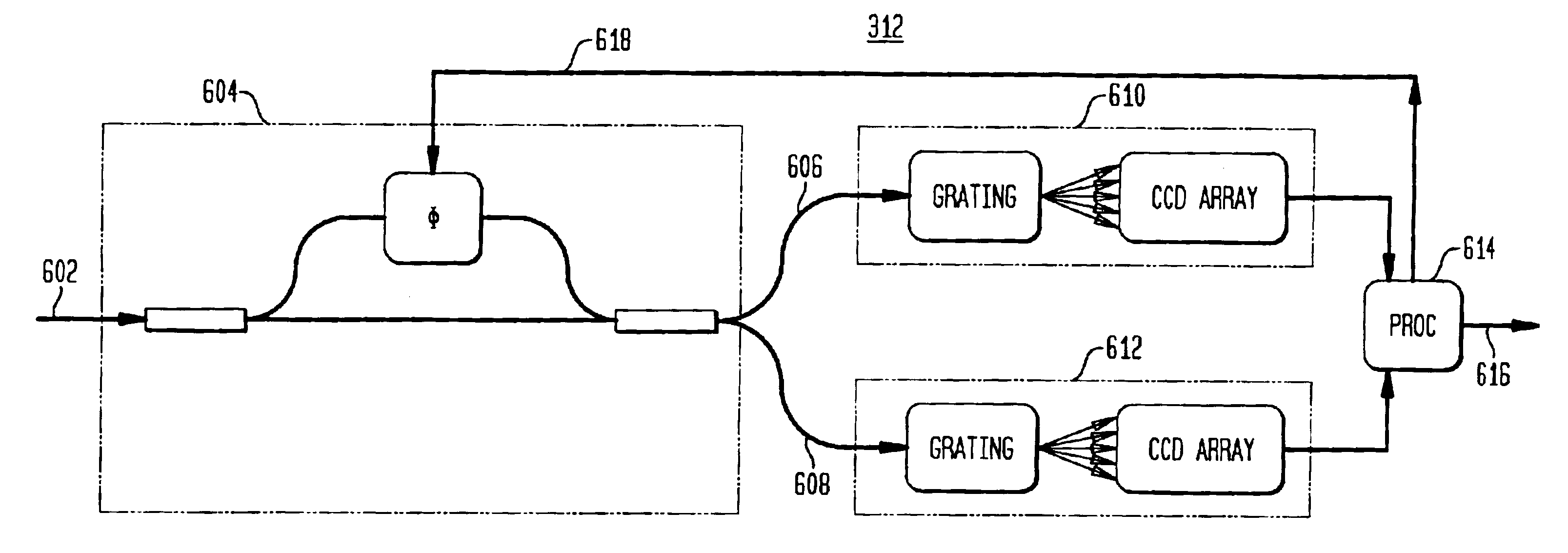
[0010]In one embodiment, the invention is an optical channel detector, comprising (a) an interferometer connected to receive an input optical signal having one or more optical channel signals and generate one or more output optical signals, wherein each output optical signals corresponds to a sum of the input optical signal and a delayed version of the input optical signal; (b) at least one spectrum analyzer connected to receive at least one output optical signal from the interferometer and generate data signals corresponding to the power of the at least one output optical signal at a plurality of different grid frequencies; and (c) a control processor connected to receive the data signals from the at least one spectrum analyzer and generate a control signal to control the delay applied by the interferometer, wherein the control processor is adapted to control the delay applied by the interferometer at one or more different settings corresponding to different degrees of constructive / destructive interference of the one or more optical channel signals at the different grid frequencies; and the control processor is adapted to compare the data signals generated by the at least one spectrum analyzer for one or more different delay settings to determine whether an optical channel signal is present in the input optical signal at each grid frequency.
[0011]In another embodiment, the invention is a method for detecting optical channels. The method involves generating one or more output optical signals from an input optical signal, wherein each output optical signals corresponds to a sum of the input optical signal and a delayed version of the input optical signal. It also involves generating data signals corresponding to the power of the at least one output optical signal at a plurality of different grid frequencies. Additionally, it involves controlling the delay applied in generating the one or more output optical signals at one or more different settings corresponding to different degrees of constructive / destructive interference of the one or more optical channel signals at the different grid frequencies; and comparing the data signals generated for one or more different delay settings to determine whether an optical channel signal is present in the input optical signal at each grid frequency.

Problems solved by technology

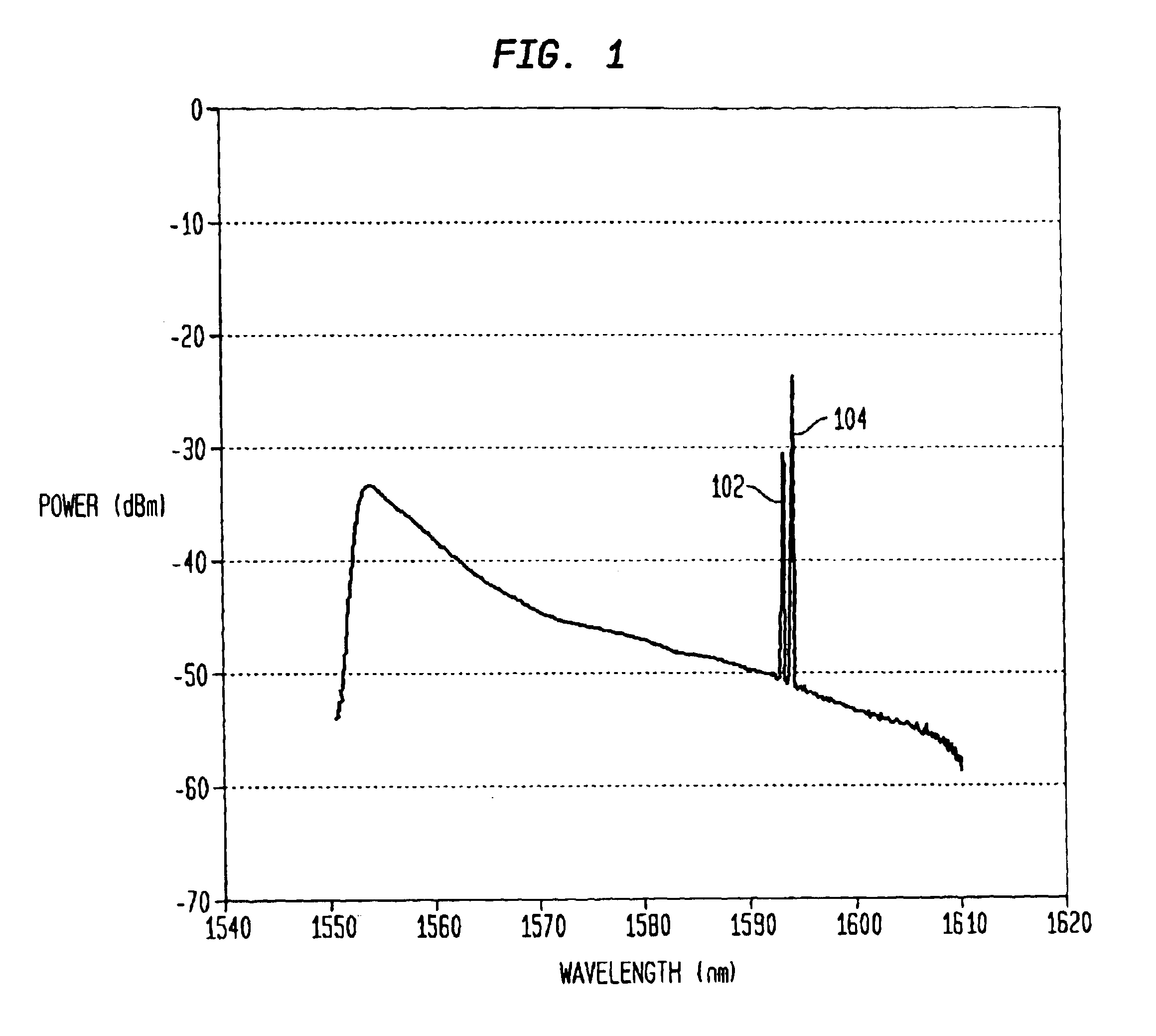
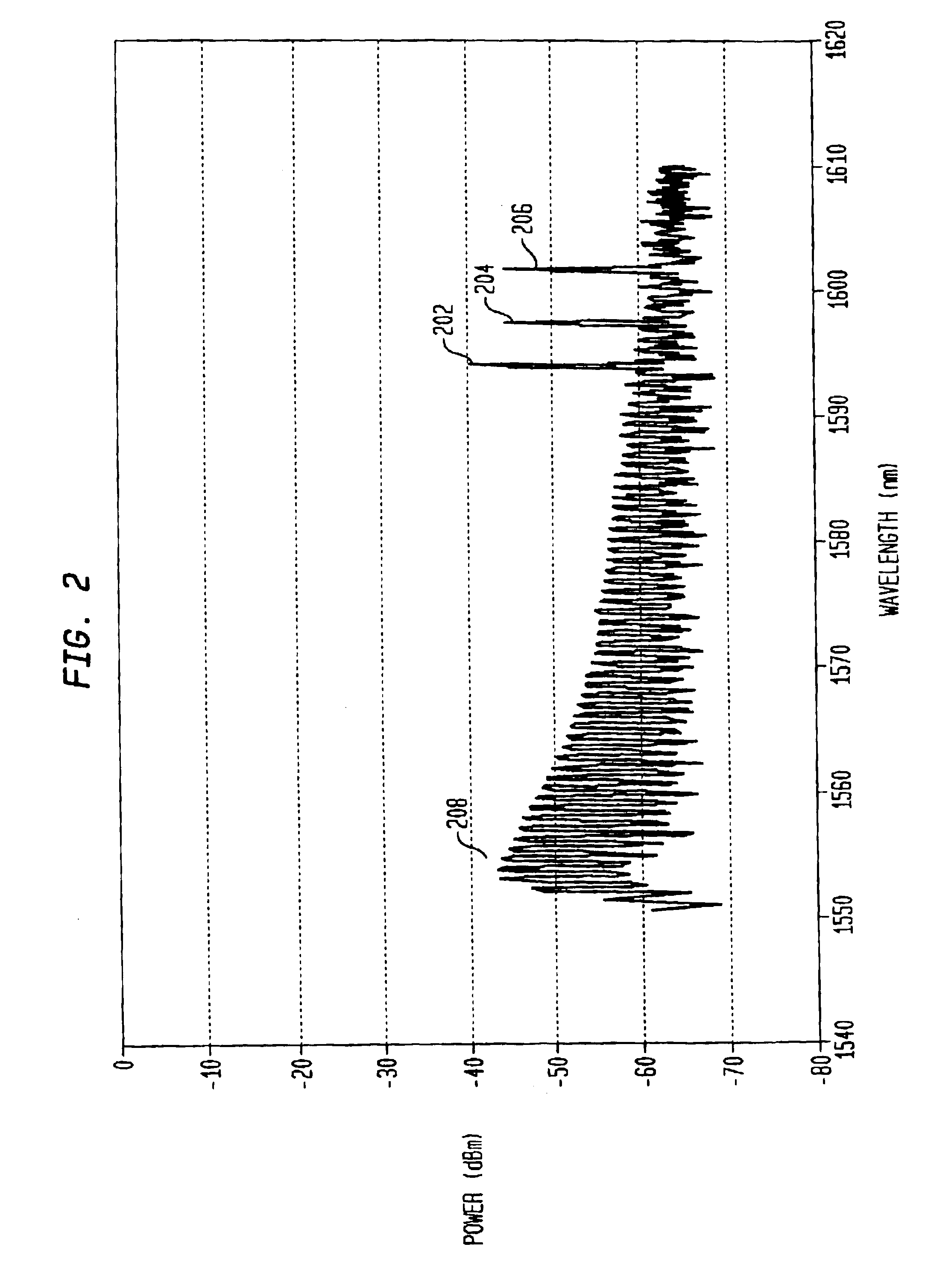
The relative delay is preferably further restricted such that the free spectral range (FSR) of the interferometer is an integer divisor of the channel-to-channel frequency spacing within the channel grid and consequently any channels present that conform to this grid experience a high degree of constructive interference.

Method used


Image

  • DWDM channel detection system
  • DWDM channel detection system
  • DWDM channel detection system

Examples


Embodiment Construction

[0020]Reference herein to “one embodiment” or “an embodiment” means that a particular feature, structure, or characteristic described in connection with the embodiment can be included in at least one embodiment of the invention. The appearances of the phrase “in one embodiment” in various places in the specification are not necessarily all referring to the same embodiment, nor are separate or alternative embodiments mutually exclusive of other embodiments.

[0021]DWDM System

[0022]FIG. 3 is a block diagram of a dense wave-division multiplexing (DWDM) optical communications system 302 according to one embodiment of this invention. System 302 includes start terminal 304, end terminal 306, intervening repeaters 308, and optical add-drop multiplexers (OADMs) 310 interconnected by fiber optic links. System 302 also includes optical monitors (OMONs) 312, each of which monitors the output of a repeater or OADM by tapping a small amount of power from its fiber optic output. Each OMON 312 also ...


PUM


Abstract

A channel detection system includes an interferometer coupled to a spectrum analyzer to differentiate additive spontaneous emission (ASE) noise from optical channels in a dense wave-division multiplex (DWDM) signal. It is assumed that channels, if present, are centered at frequencies corresponding to a standardized channel grid. The relative delay of the interferometer is chosen to be greater than the coherence time of the ASE noise but less than the coherence time of the channels with the interferometer's free spectral range set to an integer divisor of the channel-to-channel frequency spacing of the grid such that active channels experience a high degree of interference. The phase delay of the interferometer is then adjusted to maximize the interference at each grid-aligned frequency. The spectrum-analyzed outputs are compared (e.g., subtracted from one another and then thresholded) to determine the channels present in the DWDM signal.

Description

BACKGROUND OF THE INVENTION[0001]1. Field of the Invention[0002]The present invention relates to optical communication, and, more specifically, to optical channel monitors in dense wave-division multiplexing systems.[0003]2. Description of the Related Art[0004]Historically, the fibers in optical communications systems were illuminated with light consisting of one, or at most a handful, of wavelengths. With the widespread adoption of dense wave-division multiplexing (DWDM) technology, it is now common to light fibers with tens or even hundreds of different wavelengths simultaneously, each wavelength representing a different channel within the system. As the number of wavelengths and the general complexity of these systems have increased, correspondingly higher demands have been placed on the optical performance monitoring systems that are used to manage bandwidth, power, amplification, attenuation, and dynamic filtering within these systems. These optical performance monitoring syste...

Claims


Application Information

Patent Timeline
Patent Type & Authority Patents(United States)
IPC IPC(8): G01J4/00H01J5/02H01J5/16H04B10/158H04J14/02
CPCH04J14/02H04B10/66
Inventor BEGER, ALEXANDERDUTTA, RANJANHALLER, MITCHELL E.SHEN, SHUAI
Owner WSOU INVESTMENTS LLC
Learn More