Multi-band planar antenna

a planar antenna and multi-band technology, applied in the direction of resonant antennas, antenna supports/mountings, radiating element structural forms, etc., can solve the problems of omitting matching parts of known antennas, extra cost of second shorting conductors, etc., and achieves the effect of facilitating manufactur

Inactive Publication Date: 2005-06-28
CANTOR FITZGERALD SECURITIES
View PDF13 Cites 305 Cited by
  • Summary
  • Abstract
  • Description
  • Claims
  • Application Information

AI Technical Summary

Benefits of technology

[0009]An advantage of the invention is that due to the second shorting conductor the matching of a multi-band planar antenna is better accomplished than in corresponding antennas of prior art. This can be utilised by constructing a smaller antenna. A further advantage is that an antenna according to the invention is simple and advantageous to manufacture. However, the second shorting conductor means an extra cost, but on the other hand it is possible to omit matching parts of known antennas.
is that due to the second shorting conductor the matching of a multi-band planar antenna is better accomplished than in corresponding antennas of prior art. This can be utilised by constructing a smaller antenna. A further advantage is that an antenna according to the invention is simple and advantageous to manufacture. However, the second shorting conductor means an extra cost, but on the other hand it is possible to omit matching parts of known antennas.

Problems solved by technology

However, the second shorting conductor means an extra cost, but on the other hand it is possible to omit matching parts of known antennas.

Method used


Image

  • Multi-band planar antenna
  • Multi-band planar antenna
  • Multi-band planar antenna

Examples


Embodiment Construction

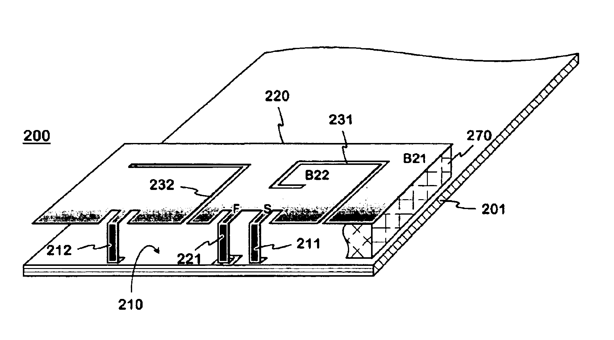
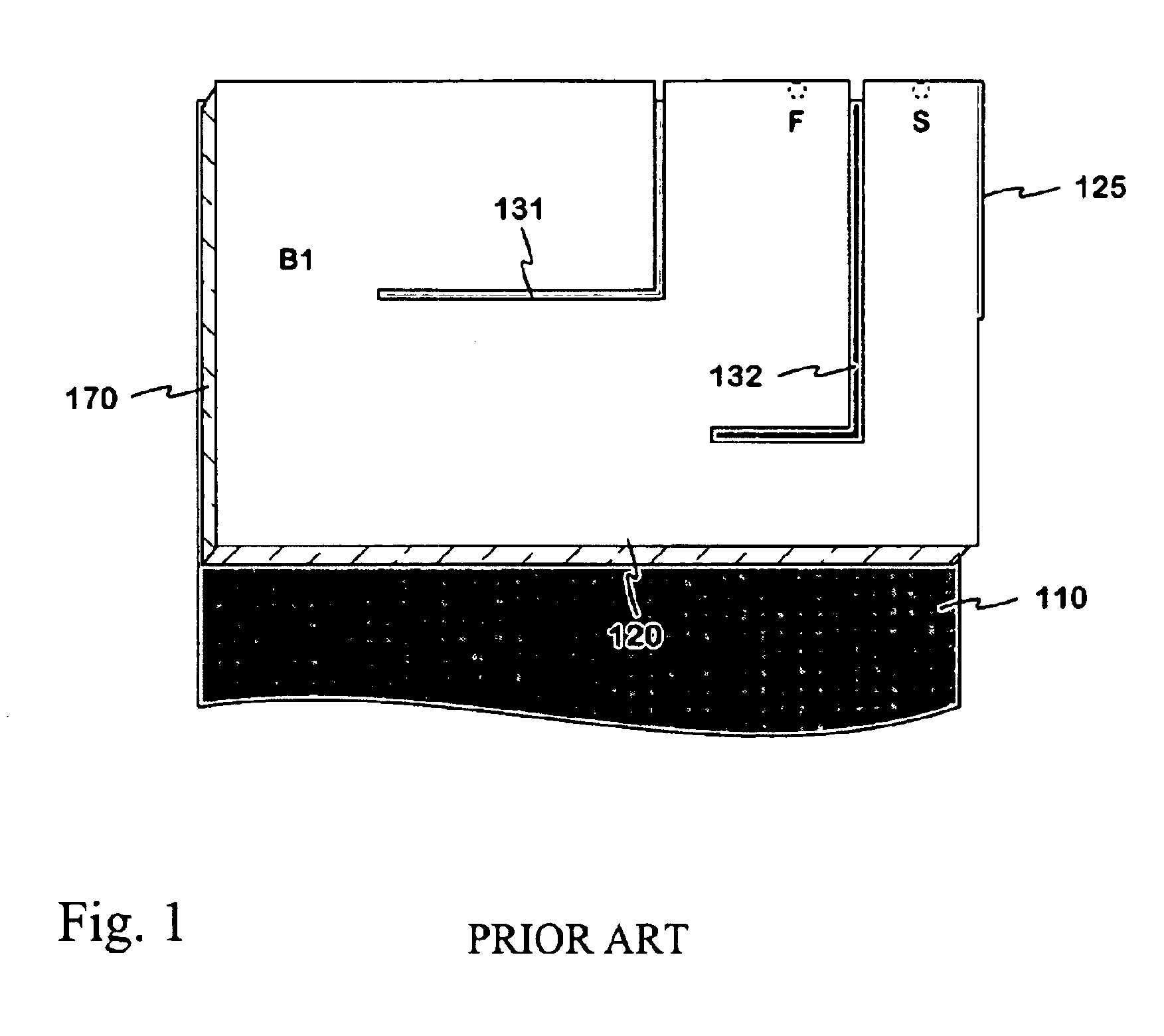
[0016]FIG. 2 shows an example of a planar antenna according to the invention. The figure shows the circuit board 201 in a radio device where the top conductive surface of the circuit board acts as the ground plane 210 of the antenna 200. A radiating planar element 220 lies above the ground plane, supported by a dielectric frame 270 on the circuit board. On one side of the planar element the antenna feeding conductor 221 is joined to it in the feeding point F and the first shorting conductor 211 in the shorting point S. In this example these conductors are of the same metal sheet with the planar element. The lower end of the shorting conductor 211 abuts of course the ground plane on the top surface of the circuit board 201. The lower end of the feeding conductor 221 seen in the figure also abuts the circuit board, but isolated from the ground it extends via a through hole to the antenna port of the radio device. The planar element 220 has a first slot 231, which is open at the elemen...


PUM


Abstract

A multi-band planar antenna applicable as an internal antenna in small-sized mobile stations, and to a radio device including an antenna according to the invention. The basis is a conventional dual band PIFA with its feeding and shorting conductors and a non-conducting slot. The planar element (220) has a second slot (232) known as such, which starts at the edge of the planar element on the other side of the feeding conductor (221) and shorting conductor (211) than the above-mentioned slot (231). In addition the structure comprises a second shorting conductor (212) on the other side of the second slot, than the feeding conductor. The second slot acts as a radiator, which for instance broadens the upper band of a dual band antenna. The second shorting conductor facilitates a better matching of a multi-band antenna than in corresponding prior art antennas. The antenna is simple, and its manufacturing costs are relatively low.

Description

[0001]The invention relates particularly to a multi-band planar antenna, which is applicable as an internal antenna in small-sized mobile stations. The invention relates also to a radio device including a planar antenna according to the invention.BACKGROUND OF THE INVENTION[0002]Mobile communications traffic is distributed over frequency bands used by several radio systems, such as different GSM systems (Global System for Mobile telecommunications). Therefore such models that operate in at least two radio systems are common among the mobile stations. The multi-band ability means of course that the design of the mobile terminals antenna will be more difficult. The design process becomes still more difficult if the antenna must be placed within the cover of the device to provide convenient use.[0003]An antenna, which is located within a small-sized radio device and which has sufficiently good radiation and receiving characteristics, is most easily realised as a planar structure: the a...

Claims


Application Information

Patent Timeline
Patent Type & Authority Patents(United States)
IPC IPC(8): H01Q9/04H01Q5/00H01Q1/24H01Q5/10H01Q5/371
CPCH01Q1/243H01Q5/371H01Q9/0442H01Q9/0421
Inventor KORVA, HEIKKI
Owner CANTOR FITZGERALD SECURITIES
Why Eureka
Try Eureka