Method for the primary control in a combined gas/steam turbine installation

a technology of combined gas and steam turbines, which is applied in the direction of steam engine plants, steam engine plants, hot gas positive displacement engine plants, etc., can solve the problems of limiting the change in gas turbine power and essentially limited load-changing capability

Inactive Publication Date: 2005-07-05
SIEMENS AG
View PDF13 Cites 19 Cited by
  • Summary
  • Abstract
  • Description
  • Claims
  • Application Information

AI Technical Summary

Benefits of technology

[0008]An object of an embodiment of the present invention is to provide a method which, in the case of the gas and steam turbine installation, also permits th

Problems solved by technology

In such operation, however, there are limits to the change in the gas turbine power.
The load-changing capability is essentially limited b

Method used


Image

  • Method for the primary control in a combined gas/steam turbine installation
  • Method for the primary control in a combined gas/steam turbine installation
  • Method for the primary control in a combined gas/steam turbine installation

Examples


Embodiment Construction

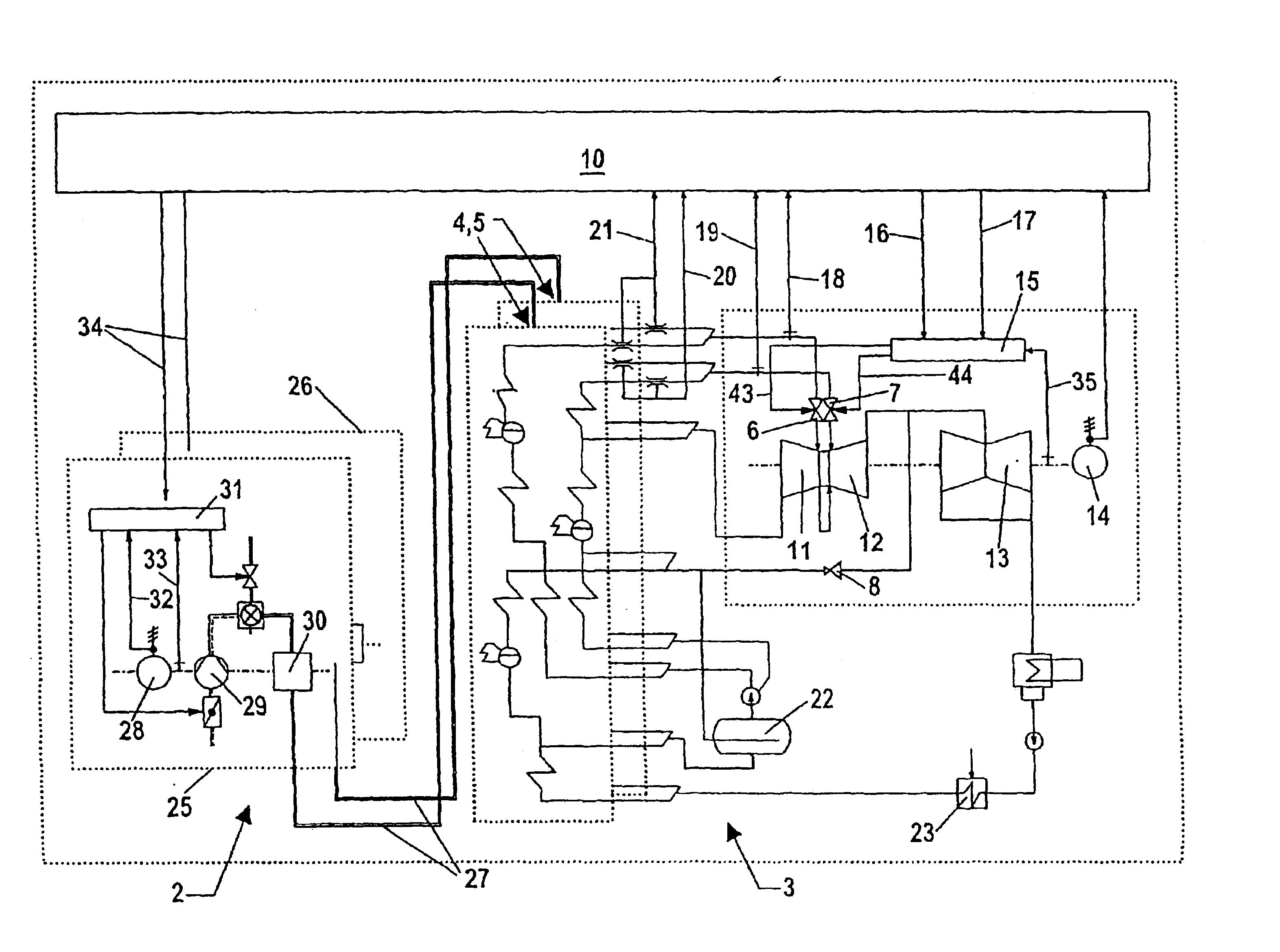
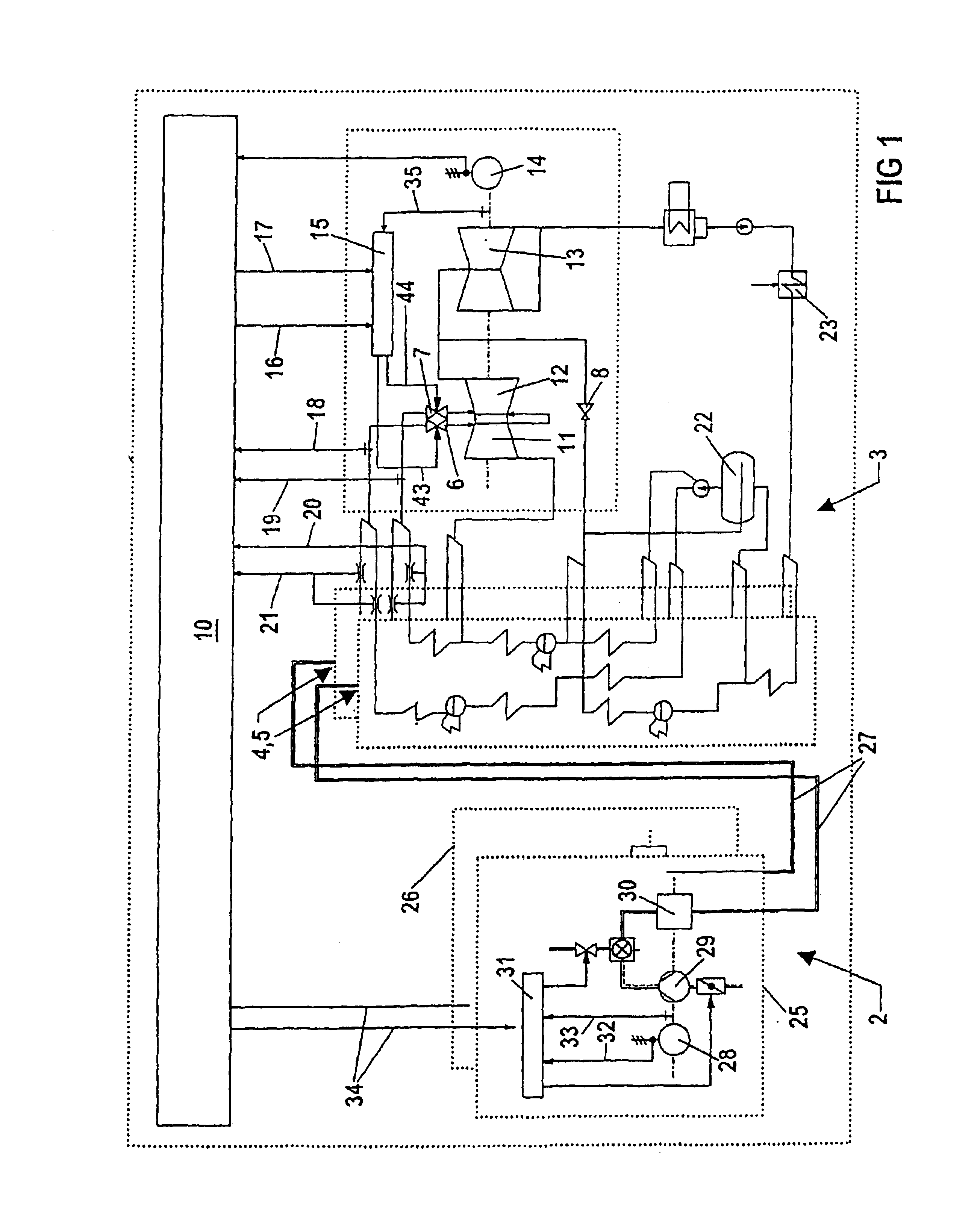
[0033]The schematic block diagram in FIG. 1 shows a gas and steam turbine installation 1, shown in an embodiment with two gas turbines, each with a downstream triple-pressure waste-heat boiler and one steam turbine. The gas and steam turbine installation 1 has a gas turbine part 2 and a steam part 3. higher level block control system 10 is provided which permits the coordinated open-loop and closed-loop control of the total gas and steam turbine installation 1. The gas turbine part 2 includes two gas turbine sets 25, 26. Each gas turbine set 25, 26 has a compressor 29, a turbine part 30 and a generator 28. A gas turbine control system 31 is provided to control the gas turbine set 25. The gas turbine sets 25, 26 obtain their required power values 34 from the block control system 10. An actual gas turbine power value 32 and an actual gas turbine rotational speed value 33 are stored in the gas turbine control system 31. The gas turbine rotational speed is used as the actual value for t...


PUM


Abstract

The aim of the invention is to improve a method for the primary control so that reserve power that is practically completely available for the effective frequency boost within seconds is available also in the stem turbine part of a gas/steam turbine installation. To this end, the pressure stage is operated with a control valve (6, 7, 8) that is throttled to such an extent that a frequency boost power reserve is built up. Said power reserve is used for frequency boosting in the event of an underfrequency by correcting the desired value depending on the underfrequency. Said corrected value corresponds to an effective area of the flow that is increased vis-â-vis the throttled condition of the control valve (6, 7, 8) and acts on the effective area of flow of the control value (6, 7, 8) with an impressed signal that approaches zero after a predetermined time. Said signal is chosen in such a manner that, despite the correction of the desired value, a stable operative condition is maintained in accordance with the response behavior of the gas/steam turbine installation to the increased effective area of flow.

Description

[0001]This application is the national phase under 35 U.S.C. §371 of PCT International Application No. PCT / E-P01 / 07653 which has an International filing date of Jul. 4, 2001, which designated the United States of America and which claims priority on German Patent Application number EP 00115684.3 filed Jul. 21, 2000, the entire contents of which are hereby incorporated herein by reference.FIELD OF THE INVENTION[0002]The invention generally relates to a method for primary control in a combined gas and steam turbine installation.BACKGROUND OF THE INVENTION[0003]A gas and steam turbine installation has a gas turbine part and a steam turbine part with at least one pressure stage. The working steam of the steam turbine part is generated by one or more waste-heat boilers fed with the waste heat from the gas turbine part. The pressure stage has at least one steam turbine control valve. In this arrangement, the control valve passage cross section is adjusted by means of a control system whos...

Claims


Application Information

Patent Timeline
IPC IPC(8): F01K23/10
CPCF01K23/108
Inventor BESCHERER, HELMUTDIEGEL, DIETERFRANK, REINHARDGOTTFRIED, PETERHENNING, MICHAELZAVISKA, OLDRICH
Owner SIEMENS AG
Why Eureka
Try Eureka