Soil compaction measurement

a technology of soil compaction and measurement method, applied in the direction of mechanical measuring arrangement, instruments, using mechanical means, etc., can solve the problems of affecting the accuracy of soil compaction measurement, and requiring substantial elapsed time for cone measurement,

Inactive Publication Date: 2005-07-05
RAYTHEON BBN TECH CORP
View PDF35 Cites 63 Cited by
  • Summary
  • Abstract
  • Description
  • Claims
  • Application Information

AI Technical Summary

Benefits of technology

[0009]Another embodiment of the present invention is directed to an apparatus for the in-situ measurement of the stiffness of a surface. The apparatus includes a weight for providing a static bias force, a contact foot for engaging the surface, and a drive transducer coupled to the foot for applying a vibratory force to the contact foot. The apparatus further includes a resilient connection between the weight and the contact foot, which statically couples the weight to the contact foot and dynamically isolates mass of the weight from motion of the contact foot due to the vibratory force applied to the contact foot.

Problems solved by technology

A sand cone measurement requires substantial elapsed time while a nuclear densitometric measurement is often not considered sufficiently reliable and also raises radiation concerns.
While it has previously been proposed to measure soil properties by dynamic impedance measurements, no such prior system has found acceptance since the readings have been found to be inconsistent and not generally repeatable.

Method used


Image

  • Soil compaction measurement
  • Soil compaction measurement
  • Soil compaction measurement

Examples


Embodiment Construction

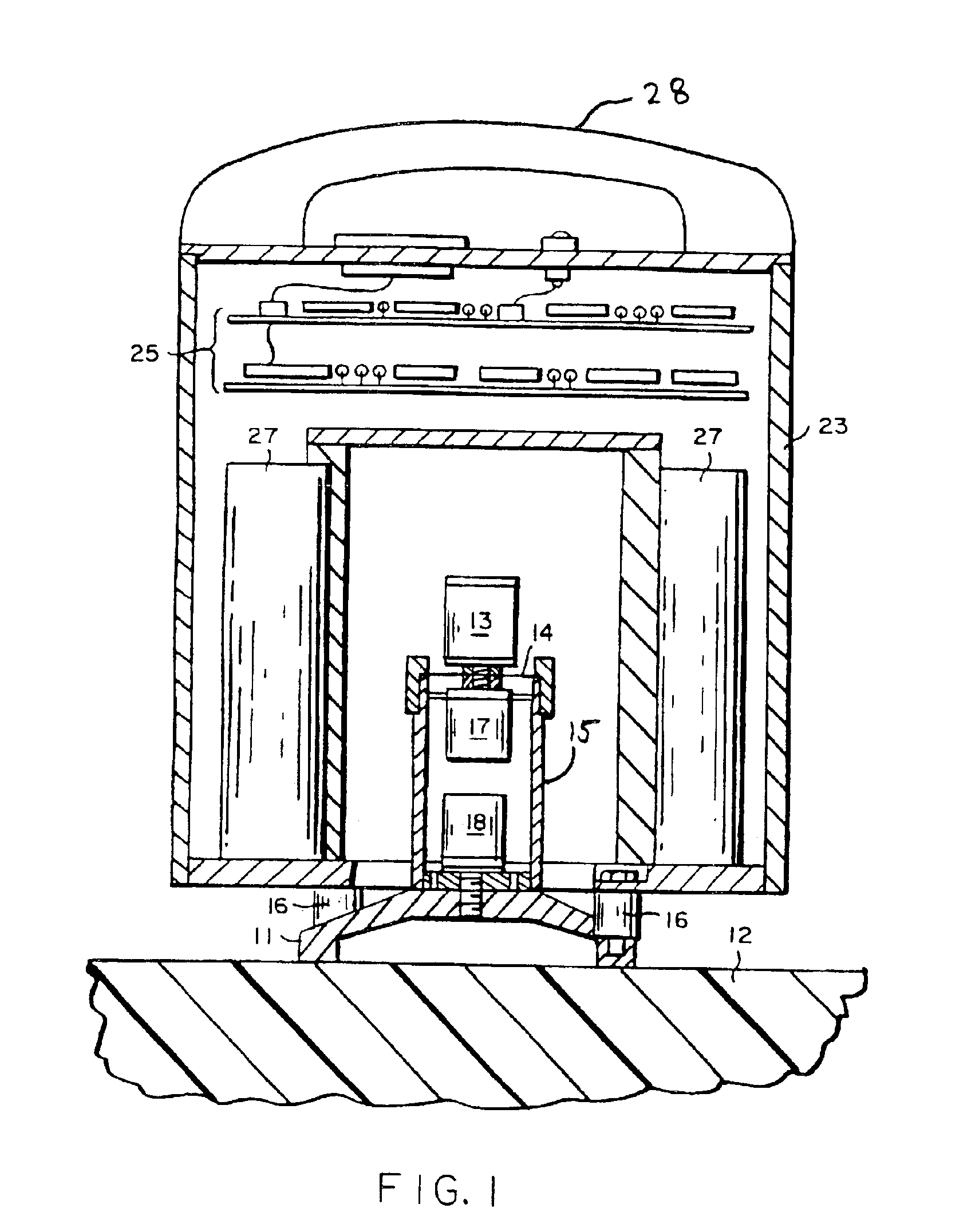
[0026]FIG. 1 illustrates an apparatus, which is intended to be man portable so that a worker can easily move it from location to location within a construction site, according to one embodiment of the present invention. The apparatus is designed to stand on a contact foot 11, which, as is described in greater detail hereinafter, engages a defined surface area or region of soil (or other surface, such as asphalt or other pavements) 12 to be tested. The effective depth of measurement of the apparatus is on the order of 1 to 2 times the nominal diameter. In the example embodiment illustrated, the diameter of the foot is about 4½ inches as is appropriate for lifts, or fill layers, up to about 12 inches. Larger or smaller foot diameters may be appropriate in alternate embodiments for measuring soils of different characteristics, providing deeper or limiting effective depth of the measurement, measuring stiffness of other types of surfaces such as pavements, and providing a foot diameter ...


PUM

PropertyMeasurementUnit
diameteraaaaaaaaaa
total weightaaaaaaaaaa
frequenciesaaaaaaaaaa

Abstract

An apparatus and method are provided for the in-situ measurement of the stiffness of a layer of soil or other surface of interest. The apparatus includes a contact foot for engaging the surface and a drive transducer coupled to the contact foot for applying a vibratory force to the contact foot in response to a drive signal. A motion sensor is coupled to the contact foot and in a preferred embodiment an additional sensor measures the force applied to the contact foot and hence to the surface. These sensors generate corresponding output signals. The output signals are used to generate a measurement signal that is representative of the surface stiffness.

Description

CROSS-REFERENCE TO RELATED APPLICATIONS[0001]This application is a continuation-in-part of U.S. application Ser. No. 09 / 530,662, filed May 2, 2000, now U.S. Pat. No. 6,604,432, which is a Section 371 National Stage Application of International Application No. PCT / US97 / 00990, filed Jan. 23, 1997 and published as WO97 / 28432, in English, which is a continuation-in-part of and claims priority from U.S. application Ser. No. 08 / 595,256, filed Feb. 1, 1996, now abandoned.FIELD OF THE INVENTION[0002]The present invention relates to the measurement of the properties of soil and more particularly to apparatus for measuring the shear modulus (or other moduli) of soil to determine the extent of compaction.BACKGROUND OF THE INVENTION[0003]As is understood, soil is an important building material. It serves as the base for virtually all pavements, tunnels and buildings, and thus, can be thought of as an element used in construction. In construction, soil will typically be specified to have certain...

Claims


Application Information

Patent Timeline
Patent Type & Authority Patents(United States)
IPC IPC(8): E02D1/00E02D1/02G01N3/32G01H15/00
CPCE02D1/02G01H15/00G01N3/32G01N2291/02827
Inventor HAMBLEN, WILLIAM R.BERKMAN, EVAN FRANKWATTERS, BILL G.WATTERS, ESTELLE
Owner RAYTHEON BBN TECH CORP
Why Eureka
Try Eureka