Carburetor arrangement

a technology of carburetor and arrangement, which is applied in the direction of heating type, separation process, application, etc., can solve the problem of not having full output, and achieve the effect of reliable coupling and convenient operation

Active Publication Date: 2005-07-05
ANDREAS STIHL AG & CO KG
View PDF20 Cites 20 Cited by
  • Summary
  • Abstract
  • Description
  • Claims
  • Application Information

AI Technical Summary

Benefits of technology

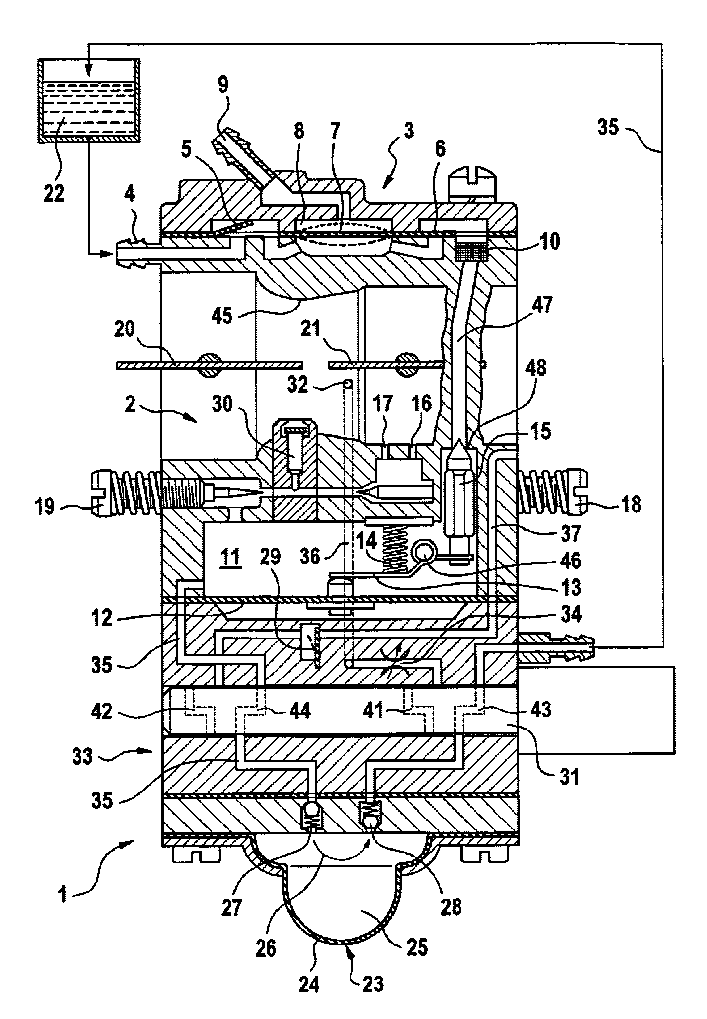
[0011]Due to the presence of the supply line from the pump chamber of the scavenging pump into the air channel, additional fuel can be supplied to the air channel. Due to the enrichment of the mixture from the pump chamber in the start-up and run-up phases of the engine, in the operating state the carburetor can be set to a lesser supply of fuel. In the full throttle range, the fuel consumption is thus reduced, whereupon the emissions are also reduced. The additional supply of fuel in the run-up phase causes the engine to already have a high output in this phase. Thus, the full output is not available only after run-up of the engine. The fuel is taken from the pump chamber of the scavenging pump. The pump chamber is thus nearly entirely emptied, so that the operator is forced to actuate the scavenging pump prior to the next start-up. This ensures that the regulating chamber is again completely filled with fuel. A filled pump chamber, which leads to the operator not actuating the scavenging pump, accompanied by simultaneous emptying of the regulating chamber, is thereby avoided.
[0012]It is provided that a first valve is disposed in the supply line that in particular in the run-up phase of the internal combustion engine is open. Thus, fuel can be supplied to the engine in this phase of operation in a precisely controlled manner. In particular, a second valve is disposed in a pressure line that opens into the pump chamber. The pressure line expediently connects the crankcase of the internal combustion engine with the pump chamber. By means of the pressure conveyed via the pressure line into the pump chamber, the discharge of fuel into the air channel is ensured. The valve permits the precise switching on and off of the pressure charge. To avoid a fuel supply from the pump chamber, via the pressure line, into the crankcase of the internal combustion engine, a check valve, especially a diaphragm check valve, is disposed in the pressure line. The first and second valves are expediently coupled in such a way that both valves are either opened or closed. By charging the scavenging pump with pressure via the pressure line, there is ensured that fuel can flow out of the pump chamber to the air channel.
[0014]It is provided that a throttle valve is disposed in the supply line. As a result, it is possible to regulate the amount of fuel additionally introduced into the air channel via the supply line. In particular, a check valve is disposed in the supply line, with the opening pressure of the check valve being greater than the pressure that during idling of the internal combustion engine prevails in the pressure line. The check valve can, for example, have an opening pressure of 100 to 600 mbar, especially 200 to 400 mbar. Due to the check valve, a supply of fuel via the supply line is prevented during idling of the internal combustion engine.
[0015]The first, second, third and fourth valves are advantageously formed in a common valve slide. In this way, the valves are reliably coupled with one another. An appropriate valve slide or rotary valve can be produced in a straightforward manner. It is robust and can be easily operated. The diaphragm carburetor is provided with a pivotably mounted butterfly valve in the air channel, and upstream of the butterfly valve has a pivotably mounted choke valve. The position of at least one valve is advantageously coupled with the position of the choke valve. In particular, with choke valve open, the first valve is opened and the third valve is closed. During start-up of the engine, the regulating chamber can thus first be flooded with fuel. The choke valve is already closed for the start-up of the engine. The engine is then started. During opening of the choke valve, the first valve is opened, so that additional fuel is conveyed to the air channel in the run-up phase.
[0016]To prevent actuation of the scavenging pump in the run-up phase and in the operating phase, a cover element is provided, the position of which is coupled to the position of the third valve, and which cover element releases the scavenging pump when the third valve is opened. This ensures that the scavenging pump can only be used to draw fuel into the regulating chamber, and a pumping of fuel into the air channel via the first valve and the supply line is prevented.

Problems solved by technology

Thus, the full output is not available only after run-up of the engine.

Method used


Image

  • Carburetor arrangement
  • Carburetor arrangement
  • Carburetor arrangement

Examples


Embodiment Construction

[0018]Referring now to the drawings in detail, illustrated in FIG. 1 is a carburetor arrangement that comprises a diaphragm carburetor 1 into which is integrated a scavenging pump module 33. The scavenging pump module 33 can, however, also be embodied separately. Formed in the diaphragm carburetor 1 is an air channel 2 in which are disposed a rotatably or slidably mounted choke valve 20 and, downstream of the choke valve, a butterfly valve 21. The air channel 2 is provided in particular in the region between the choke valve 20 and the butterfly valve 21 with a venturi section 45. A primary idling nozzle opens out in the region of the butterfly valve 21, and upstream of the primary idling nozzle 16 a secondary idling nozzle 17 opens out into the air channel 2. With the butterfly valve 21 closed, the primary idling nozzle 16 is disposed downstream of the butterfly valve 21 and the secondary idling nozzle 17 is disposed upstream of the butterfly valve 21.

[0019]A main nozzle 30 opens ou...


PUM

PropertyMeasurementUnit
Pressureaaaaaaaaaa
Pressureaaaaaaaaaa

Abstract

A carburetor arrangement for an internal combustion engine in a manually guided implement, such as a power chainsaw, a cut-off machine, etc. is provided. A regulating chamber delimited by a regulating diaphragm is provided. Upon deflection of the diaphragm due to underpressure in the regulating chamber, the latter is connected with a fuel tank. Via at least one nozzle, the regulating chamber opens into an air channel that supplies fuel / air mixture to the engine. The carburetor arrangement includes a scavenging pump that is disposed in a return line from the regulating chamber to the fuel tank, and in which is formed a pump chamber. The scavenging pump serves to completely fill the regulating chamber with fuel before start-up of the engine. To prevent the fuel / air mixture from becoming too lean after start-up, especially upon opening of the choke valve, a supply line is provided from the pump chamber into the air channel and supplies additional fuel to the air channel during the run-up phase.

Description

BACKGROUND OF THE INVENTION[0001]The present invention relates to a carburetor arrangement for an internal combustion engine in a manually guided implement, such as a power chainsaw, a cut-off machine, or the like.[0002]EP 0 786 591 discloses a carburetor arrangement that includes a scavenging pump and an injection pump as the actual starting aid. By actuating the injection pump, fuel can be introduced into the intake channel prior to starting the engine. As a result, an adequate supply of fuel to the internal combustion engine is intended to be achieved already for the first ignitions without a choke. The injected quantity of fuel is, however, consumed as the engine starts.[0003]An internal combustion engine is generally started with the choke valve closed. If, after start-up of the engine, the choke valve is opened too rapidly, the mixture can become too lean, especially with a cold engine. As a consequence, the engine stalls. A renewed starting with the choke closed can lead to t...

Claims


Application Information

Patent Timeline
IPC IPC(8): F02M1/00F02M1/16F02M17/00F02M17/04F02M1/02
CPCF02M1/02F02M1/16F02M17/04Y10S261/68
Inventor OSBURG, GERHARDGANTERT, JOCHENGERHARDY, REINHARD
Owner ANDREAS STIHL AG & CO KG
Why Eureka
Try Eureka