
Slurry bubble reactor operated in well-mixed gas flow regime

Inactive Publication Date: 2005-07-05
CONOCOPHILLIPS CO
View PDF14 Cites 19 Cited by
  • Summary
  • Abstract
  • Description
  • Claims
  • Application Information

AI Technical Summary

Benefits of technology

[0016]It is illustrated in the present invention that high catalyst productivity and reactor capacity can be achieved by operating at a high gas input and an intermediate single pass conversion. At a high gas input, the gas phase will be in well-mixed flow regime. However, at the intermediate conversion range, say conversion from 35% to 75%, the reactor volume required for the well-mixed gas flow is close to that for the plug flow regime. There are many advantages of choosing the well-mixed gas regime for the FT synthesis as shown in the current invention.
[0017]The present invention provides a gas-agitated multiphase reactor system that is effective for enabling maximum reactor productivity and / or minimizing reactor volume.

Problems solved by technology

However, most natural gas is situated in areas that are geographically remote from population and industrial centers.
The costs of compression, transportation, and storage make its use economically unattractive.
Therefore, the gas dispersion coefficient is also a complicated function of these design and operating parameters.
To maintain a plug flow for achieving the high conversion requires the use of a lower gas input into the reactor, which in turn reduces the reactor productivity significantly.

Method used


Image

  • Slurry bubble reactor operated in well-mixed gas flow regime
  • Slurry bubble reactor operated in well-mixed gas flow regime
  • Slurry bubble reactor operated in well-mixed gas flow regime

Examples


example 1

High Catalyst Productivity and Space Time Yield at Low Gas Peclet Number (Thus, a Well-Mixed Gas Flow Regime)

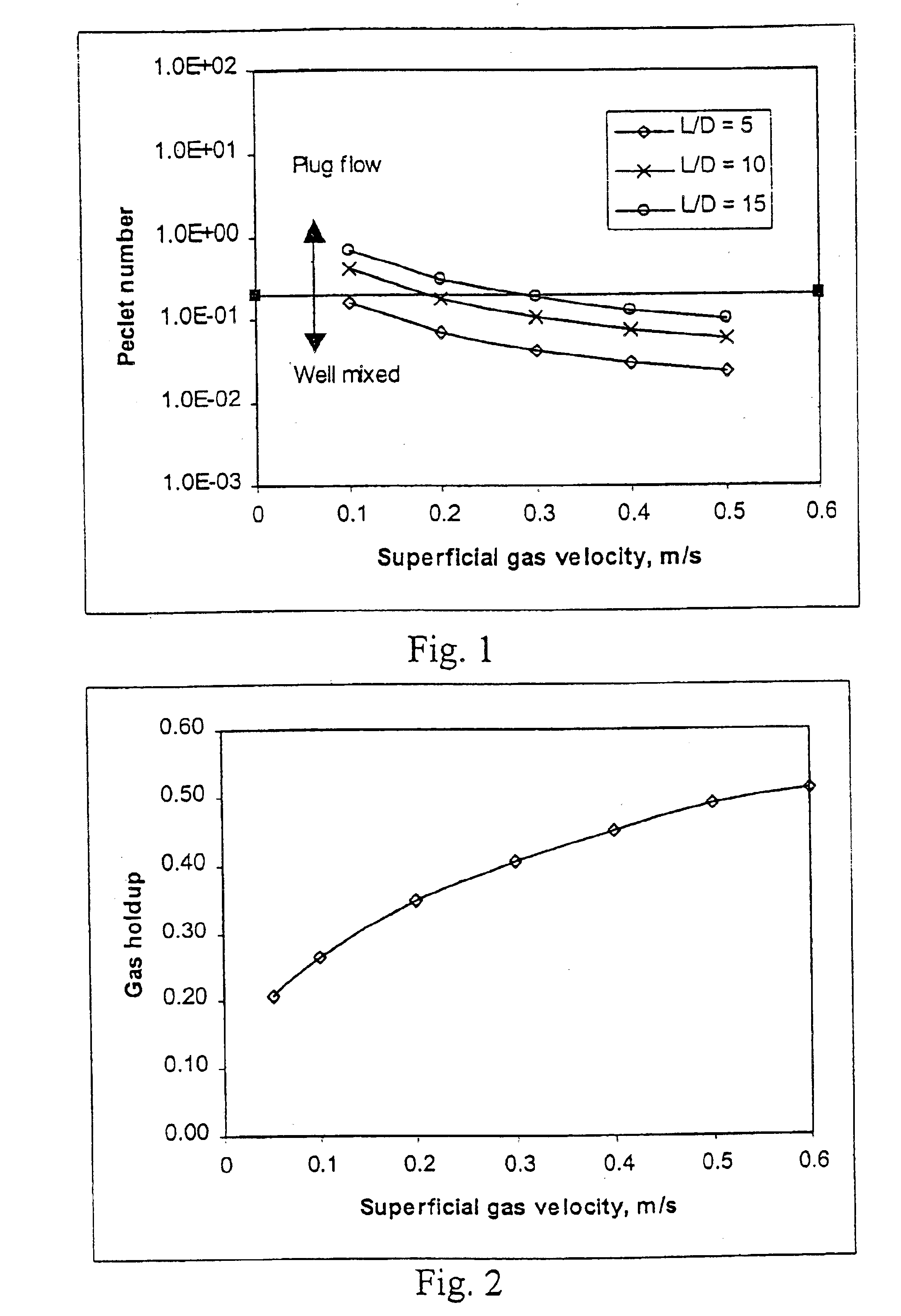
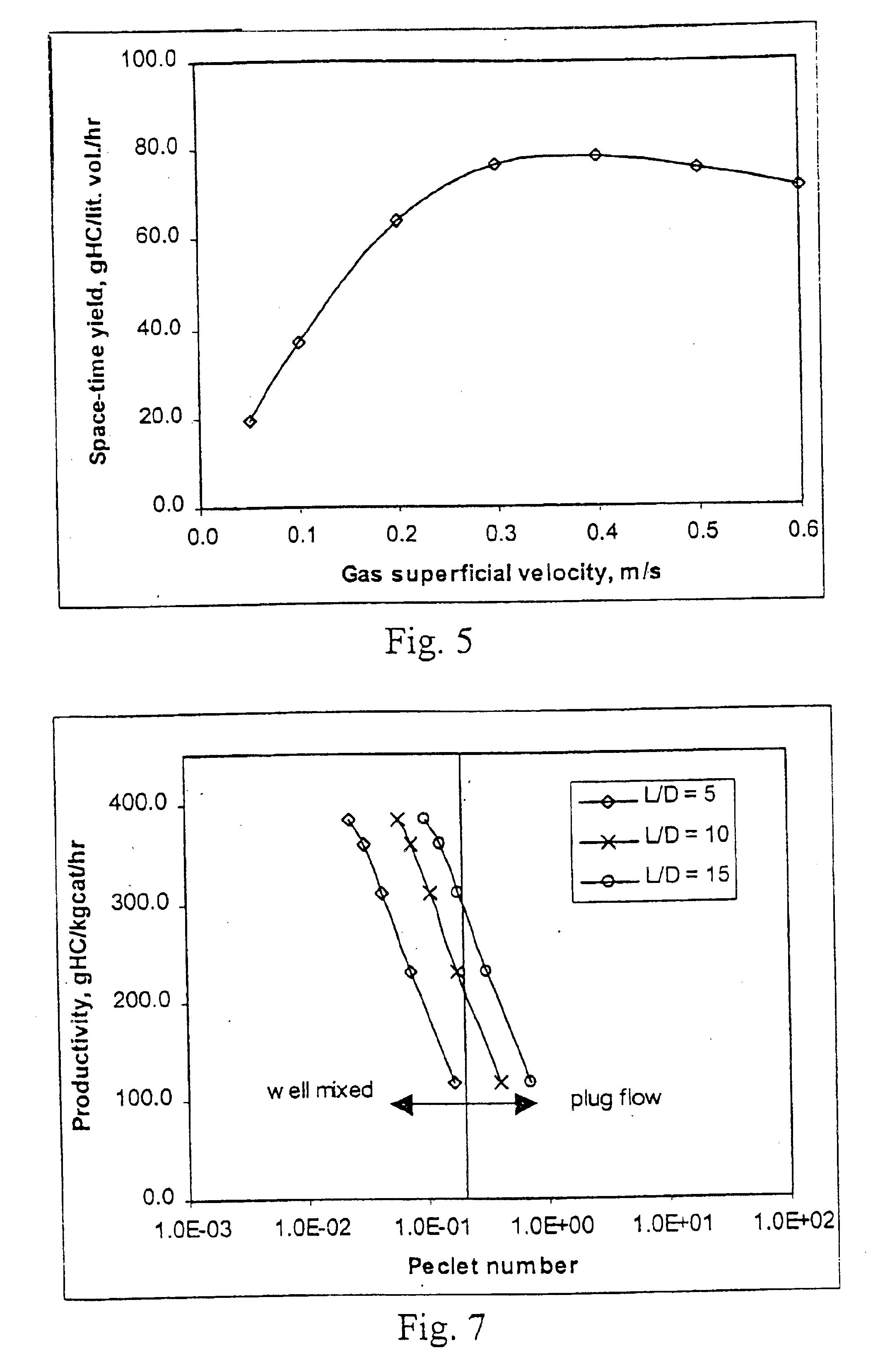
[0043]FIG. 7 shows the effect of the Peclet number on catalyst productivity at different aspect ratios. It is shown that the productivity decreases with an increase in the gas Peclet number. The higher catalyst productivity requires less catalyst to achieve the certain conversion.

[0044]Similarly, as shown in FIG. 8, the space time yield decreases significantly with the increase of the Peclet number. It is also clear from FIG. 8 that a lower gas Peclet number is directly related to a lower reactor volume needed to achieve the same product yields.

example 2

Intermediate Syngas Conversion in a Well-Mixed Gas Flow Regime

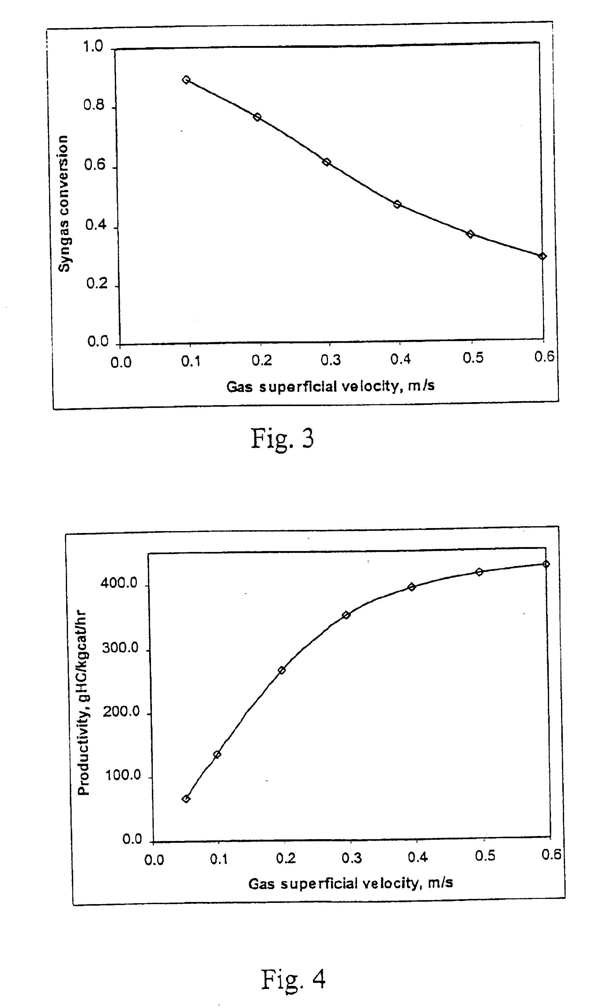
[0045]FIG. 9 illustrates the effect of the gas Peclet number on syngas conversion at different aspect ratios. Combining this analysis with the results of catalyst productivity and space time yield (FIGS. 7 and 8), we have found that an optimum design of the slurry bed reactor falls in the low Peclet number with the intermediate syngas conversion.

example 3

Lower H2O Partial Pressure and Therefore Lower Catalyst Deactivation Rate

[0046]As shown in FIG. 10, the outlet H2O partial pressure increases with an increase in the gas Peclet number. The high H2O partial pressure gives a high catalyst deactivation rate for most FT synthesis, which is undesirable. Hence, a FT slurry bed reactor at well-mixed gas flow gives a lower H2O partial pressure and therefore less catalyst deactivation rate and longer catalyst life.


PUM

PropertyMeasurementUnit
Fractionaaaaaaaaaa
Fractionaaaaaaaaaa
Fractionaaaaaaaaaa

Abstract

A gas-agitated multiphase reactor system for the synthesis of hydrocarbons gives high catalyst productivity and reactor capacity. The system includes operating a multi-phase reactor in the well-mixed gas flow regime, with a Peclet number less than 0.175 and a single pass conversion ranging from 35% to 75%, wherein the inlet superficial gas velocity decreases with the decreasing of the reactor aspect ratio, and is preferably at least 20 cm / sec.

Description

CROSS-REFERENCE TO RELATED APPLICATIONS[0001]Not applicable.STATEMENT REGARDING FEDERALLY SPONSORED RESEARCH OR DEVELOPMENT[0002]Not applicable.TECHNICAL FIELD OF THE INVENTION[0003]The present invention relates to a process for the preparation of hydrocarbons from synthesis gas, i.e., a mixture of carbon monoxide and hydrogen, typically labeled the Fischer-Tropsch process. More particularly, this invention relates to slurry bubble reactors that can maximize the production rate and / or reduce the reactor volume in a Fischer-Tropsch process. Still more particularly, this invention relates a method that provide the optimum design and operation of slurry bubble reactors that can maximize the production rate and / or reduce the reactor volume in a Fischer-Tropsch process.BACKGROUND[0004]Large quantities of methane, the main component of natural gas, are available in many areas of the world, and natural gas is predicted to outlast oil reserves by a significant margin. However, most natural ...

Claims


Application Information

Patent Timeline
IPC IPC(8): C07C1/04C07C27/00C07C27/06C07C1/00C10G2/00F25J
CPCC10G2/342
Inventor ZHANG, JIANPINGESPINOZA, RAFAEL L.MOHEDAS, SERGIO
Owner CONOCOPHILLIPS CO
Learn More