Assembly and method for direct cooling of motor end-winding

a technology of end-windings and assembly methods, which is applied in the direction of magnetic circuit rotating parts, lighting and heating apparatus, and magnetic circuit shapes/forms/construction, etc. it can solve the problems of generating heat by mechanical friction and electrical resistance, reducing the thermal resistance of heat paths proximate to electric motor end-windings, and reducing heat paths. thermal resistance, the effect of reducing the thermal resistance of heat paths

Inactive Publication Date: 2005-07-05
SIEMENS VDO AUTOMOTIVE CORP
View PDF22 Cites 19 Cited by
  • Summary
  • Abstract
  • Description
  • Claims
  • Application Information

AI Technical Summary

Benefits of technology

[0011]The inventors have noted that the thermal resistance of heat paths proximate to electric motor end-windings can advantageously be reduced. Accordingly, the inventors have devised various embodiments of methods and systems that provide, as some of their many advantages, the advantage of reducing the thermal resistance of heat paths proximate to electric motor end-windings and the advantage of providing greater cooling of electric motors.

Problems solved by technology

Electric motors are not one hundred percent efficient as they convert electrical power into mechanical power.
Specifically, mechanical friction and electrical resistance tend to create losses generating heat.
Generated heat has numerous deleterious effects.
For example, generated heat tends to increase both mechanical friction and electrical resistance within the motor, thereby creating a process which tends to feed on itself and create yet more mechanical friction and electrical resistance, thereby engendering yet more losses.
Furthermore, modern power system components (e.g., electronic control and measurement components and motor insulation) tend to degrade more rapidly in the presence of high heat.

Method used


Image

  • Assembly and method for direct cooling of motor end-winding
  • Assembly and method for direct cooling of motor end-winding
  • Assembly and method for direct cooling of motor end-winding

Examples


Embodiment Construction

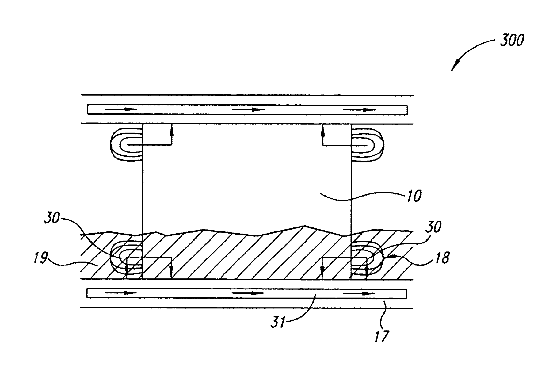
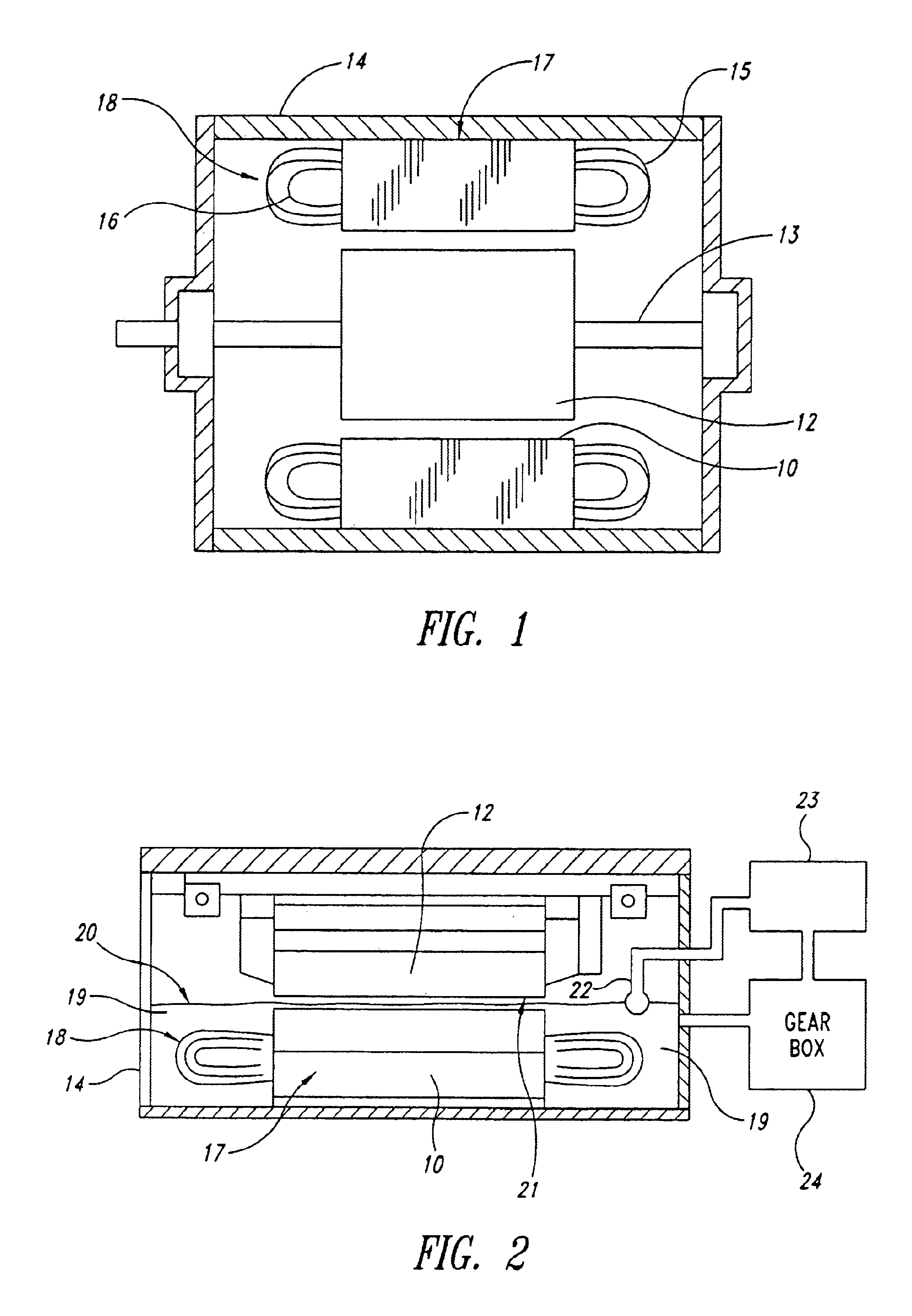
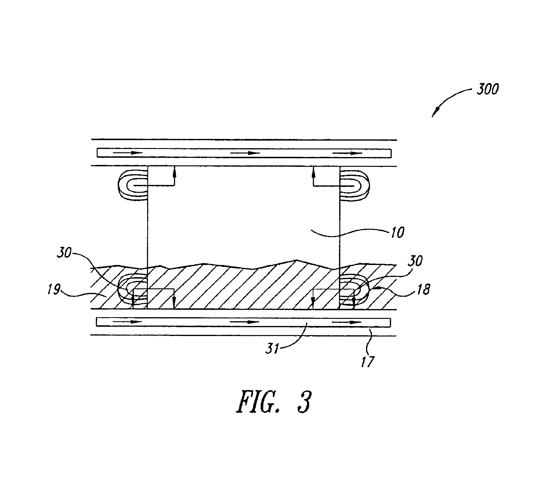
[0024]FIG. 1 shows a representation of one embodiment of an electric motor. The motor includes a stator core 10 a rotor 12, a shaft 13 of the rotor 12, and a motor housing 14. The housing 14 is sealed to prevent entry of external contaminants into the motor assembly. The stator core 10 has winding 15 formed by winding a wire 16 around a core with a predetermined electrical specification. The wire 16 may have an enameled coating outside which functions as insulation. Passing an electric current through winding 15 from the outside generates an electromagnetic force which rotates the rotor 12. The rotor 12 may, or may not, include fan blades formed or attached onto the end or ends of the rotor 12. The winding 15 consists of intimately wound wire 16 and maybe impregnated with varnish to avoid flexing. The winding 15 is a differentiator between motor designs, and has a great deal to do with the performance of the motor. The winding 15 is inserted into the steel stator core 10. The core i...


PUM


Abstract

Methods and related systems providing removal of heat from electric motors via fluid baths.

Description

CROSS-REFERENCE TO RELATED APPLICATION[0001]This application claims the benefit under 35 U.S.C. § 119(e) of the U.S. Provisional Patent Application No. 60 / 319,081 filed 16 Jan. 2002, entitled Assembly And Method For Direct Cooling Of Motor End-Winding, such application hereby incorporated by reference in its entirety.BACKGROUND OF THE INVENTION[0002]1. Field of the Invention[0003]The present application generally relates to a method and system for use with electric motors.[0004]2. Description of the Related Art[0005]Electric motors are power conversion devices. Electric motors typically convert electrical power into some type of mechanical power.[0006]Electric motors typically have two primary parts: a stator and a rotor. The “stator” is a mechanically non-moving or stationary part of the motor. The rotor is a mechanically moving or rotating part. Typically, the rotor is formed in roughly the shape of a cylinder and is surrounded by the stator, which is also typically roughly shaped...

Claims


Application Information

Patent Timeline
Patent Type & Authority Patents(United States)
IPC IPC(8): B60K6/04B60K6/00H02K5/20H02K9/19H02K9/193B60K6/26B60K6/40B60K6/405
CPCB60K6/26B60K6/40B60K6/405H02K5/20H02K9/19H02K9/193B60K2001/003Y10S903/951Y10S903/906Y10S903/952H02K5/203
Inventor SENIAWSKI, DAVIDCARDINAL, JASON M.AHMED, SAYEED
Owner SIEMENS VDO AUTOMOTIVE CORP
Why Eureka
Try Eureka