Spindle motor and disk drive furnished therewith

a technology of spindle motor and disk drive, which is applied in the direction of sliding contact bearings, instruments, record information storage, etc., can solve the problems of vibration incidents and deterioration, drop in oil internal pressure, and impair the endurance and reliability of spindle motors

Active Publication Date: 2005-07-05
NIPPON DENSAN CORP
View PDF33 Cites 54 Cited by
  • Summary
  • Abstract
  • Description
  • Claims
  • Application Information

AI Technical Summary

Benefits of technology

[0012]An object of the present invention is to realize a miniature, low-

Problems solved by technology

With dynamic-pressure bearings in a full-fill structure, when the rotor a begins rotating, pumping by the dynamic-pressure-generating grooves dl, d1 and g1, g1 acts to draw oil in toward the center areas of each of the radial bearing sections d, d and thrust bearing sections g, g, peaking the fluid dynamic pressure in the bearing center areas; but the downside of this is that along the bearing edge areas the oil internal pressure drops.
This leakage impairs the endurance and reliability of the spindle motor.
Negative pressure occurring within the oil can also lead to the dynamic-pressure-generating grooves coming into contact with air bubbles, which invites vibration inci

Method used


Image

  • Spindle motor and disk drive furnished therewith
  • Spindle motor and disk drive furnished therewith
  • Spindle motor and disk drive furnished therewith

Examples


first embodiment

I. First Embodiment

(1)Configuration of Spindle Motor

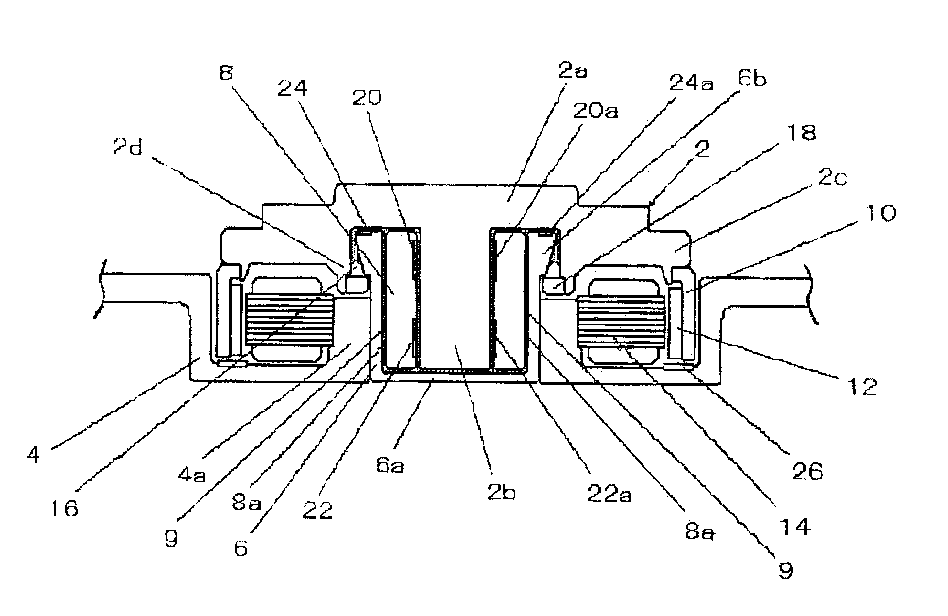
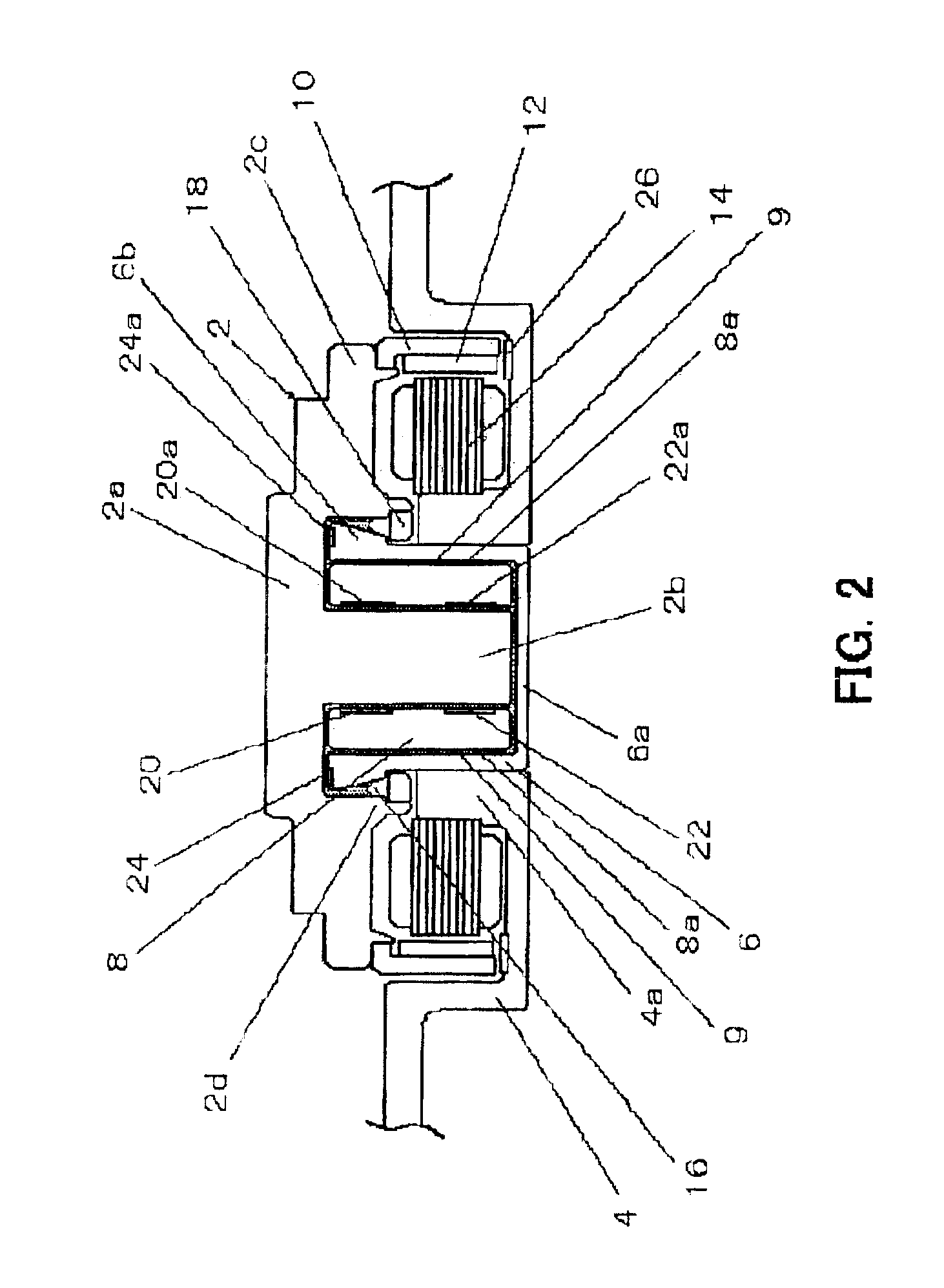
[0034]To begin with, a spindle motor in a first embodiment of the present invention will be explained with reference to FIGS. 2 through 4. The spindle motor in the first embodiment of the present invention includes: a rotor 2, composed of a rotor hub 2a and a shaft 2b provided coaxially with the rotational center of the rotor hub 2a; a cylindrical housing 6 affixed into a circular boss part 4a with which a bracket 4 is furnished; and a hollow similarly cylindrical sleeve 8 mounted within the housing 6. The circumferential margin of the rotor hub 2a is furnished with a flange-shaped disk-carrying section 2c on which recording disks (illustrated as disks 53 in FIG. 8) such as a hard disk are carried, and a yoke 10 is fitted along the undersurface of the disk-carrying section 2c. A rotor magnet 12 is attached by adhesive or like means to the inner peripheral surface of the yoke 10. Also, a stator 14 radially opposing the rotor magnet ...

second embodiment

II. Second Embodiment

[0071]With reference to FIGS. 5 through 7, explanation concerning a spindle motor in a second embodiment of the present invention will be made.

(1)Configuration of Spindle Motor

[0072]In the foregoing first embodiment, a spindle motor was described having a configuration in which a porous sintered metal is utilized as the material for the sleeve 8, and in which the communicating passages 9 are formed by the combining of the sleeve 8 and the housing 6. The spindle motor that will be described in the following in the second embodiment has a configuration in which the sleeve is formed from an aluminum alloy, a copper alloy, or stainless steel, thereby rendering the housing set out in the first embodiment unnecessary. The fact that the spindle motor in the second embodiment thus does not require the housing makes it possible to curtail the number of motor parts, and to curtail the number of motor assembly steps.

[0073]The spindle motor illustrated in FIG. 5 is equipped...


PUM


Abstract

In a spindle motor utilizing dynamic-pressure bearings having a full-fill structure, a bearing configuration that balances and sustains at or above atmospheric pressure the internal pressure of the bearing oil. Thrust and radial bearing sections are configured within oil-filled bearing clearances in between the rotor, the shaft, and a shaft-encompassing hollow bearing member. A communicating passage one end of which opens on, radially inwardly along, the thrust bearing section is formed in the bearing member. Either axial ends of the bearing clearance in between the bearing member and shaft communicate through the passage. The communicating passage enables the oil to redistribute itself within the bearing clearances. Pressure difference between the axial upper and lower ends of the oil retained in between the bearing member and the shaft is compensated through the communicating passage, preventing incidents of negative pressure within the oil and of over-lift on the rotor.

Description

BACKGROUND OF INVENTION[0001]1. Technical Field[0002]The present invention relates to spindle motors employing dynamic-pressure bearings in which oil is the working fluid, and to disk drives equipped with such spindle motors. The invention relates in particular to miniature, low-profile spindle motors that drive recording disks 2.5 inches and under, and to disk-drives equipped with such spindle motors.[0003]2. Description of the Related Art[0004]Dynamic-pressure bearings in which the fluid pressure of a lubricating fluid such as oil interposed in between the shaft and the sleeve is exploited in order to support the two letting the one rotate against the other have been proposed to date as bearings for spindle motors employed in disk drives that drive hard disks and like recording disks.[0005]FIG. 1 depicts one example of a spindle motor employing dynamic-pressure bearings. This spindle motor in which conventional dynamic pressure bearings are employed is configured with a pair of ax...

Claims


Application Information

Patent Timeline
IPC IPC(8): F16C33/04F16C33/10F16C17/04F16C17/02H02K5/16F16C17/10G11B19/20H02K7/08H02K21/22
CPCF16C17/107F16C33/107F16C33/1085H02K5/1675F16C2370/12
Inventor TOKUNAGA, SHINYAUENOSONO, KAORUNISHIMURA, HIDEKIOKU, YOSHITO
Owner NIPPON DENSAN CORP
Why Eureka
Try Eureka