Method and apparatus for aligning optical wireless links

a technology of optical wireless link and alignment method, applied in the field of optical wireless communication, can solve the problems of limited distance that such high-frequency communications can travel, physical installation and maintenance costs, and each of these conventional communications facilities involves certain limitations in their deployment, so as to achieve automatic optimization of signal reliability and signal to noise ratio, and the effect of extending the establishment of communication

Inactive Publication Date: 2005-07-05
TEXAS INSTR INC
View PDF4 Cites 16 Cited by
  • Summary
  • Abstract
  • Description
  • Claims
  • Application Information

AI Technical Summary

Benefits of technology

[0020]The preferred embodiments of the present invention provide the advantage of an optical wireless link that can acquire a line-of-sight communication with another optical wireless link without user intervention.
[0021]Additionally, the preferred embodiments provide the advantage that the optical wireless links can be aligned to each other quickly, in order to expedite the establishment of communication between them.
[0022]Another provided advantage is the ability to re-acquire the line-of-sight communication in the event of an unexpected event, such as one or both of the optical wireless links being bumped or disturbed in some manner.
[0023]Another provided advantage is the ability for the optical wireless link to automatically optimize signal reliability and signal to noise ratio by having the optical wireless link re-position its beam based upon feedback signals from the beam receiving device.

Problems solved by technology

Each of these conventional communications facilities involves certain limitations in their deployment.
In the case of communications over the telephone network, high-speed data transmission, such as that provided by digital subscriber line (DSL) services, must be carried out at a specific frequency range to not interfere with voice traffic, and is currently limited in the distance that such high-frequency communications can travel.
This physical installation and maintenance is costly, as well as limiting to the user of the communications network.
Conventional wireless technologies involve their own limitations, however.
Furthermore, current wireless telephone communication of large data blocks, such as video, is prohibitively expensive, considering the per-unit-time charges for wireless services.
Additionally, wireless telephone communications are subject to interference among the various users within the nearby area.
Radio frequency data communication must also be carried out within specified frequencies, and is also vulnerable to interference from other transmissions.
Satellite transmission is also currently expensive, particularly for bi-directional communications (i.e., beyond the passive reception of television programming).
As opposed to fiber optic-based optical communications, however, this approach does not use a physical wire for transmission of the light signal.

Method used


Image

  • Method and apparatus for aligning optical wireless links
  • Method and apparatus for aligning optical wireless links
  • Method and apparatus for aligning optical wireless links

Examples


Embodiment Construction

[0033]The making and use of the various embodiments are discussed below in detail. However, it should be appreciated that the present invention provides many applicable inventive concepts, which can be embodied in a wide variety of specific contexts. The specific embodiments discussed are merely illustrative of specific ways to make and use the invention, and do not limit the scope of the invention.

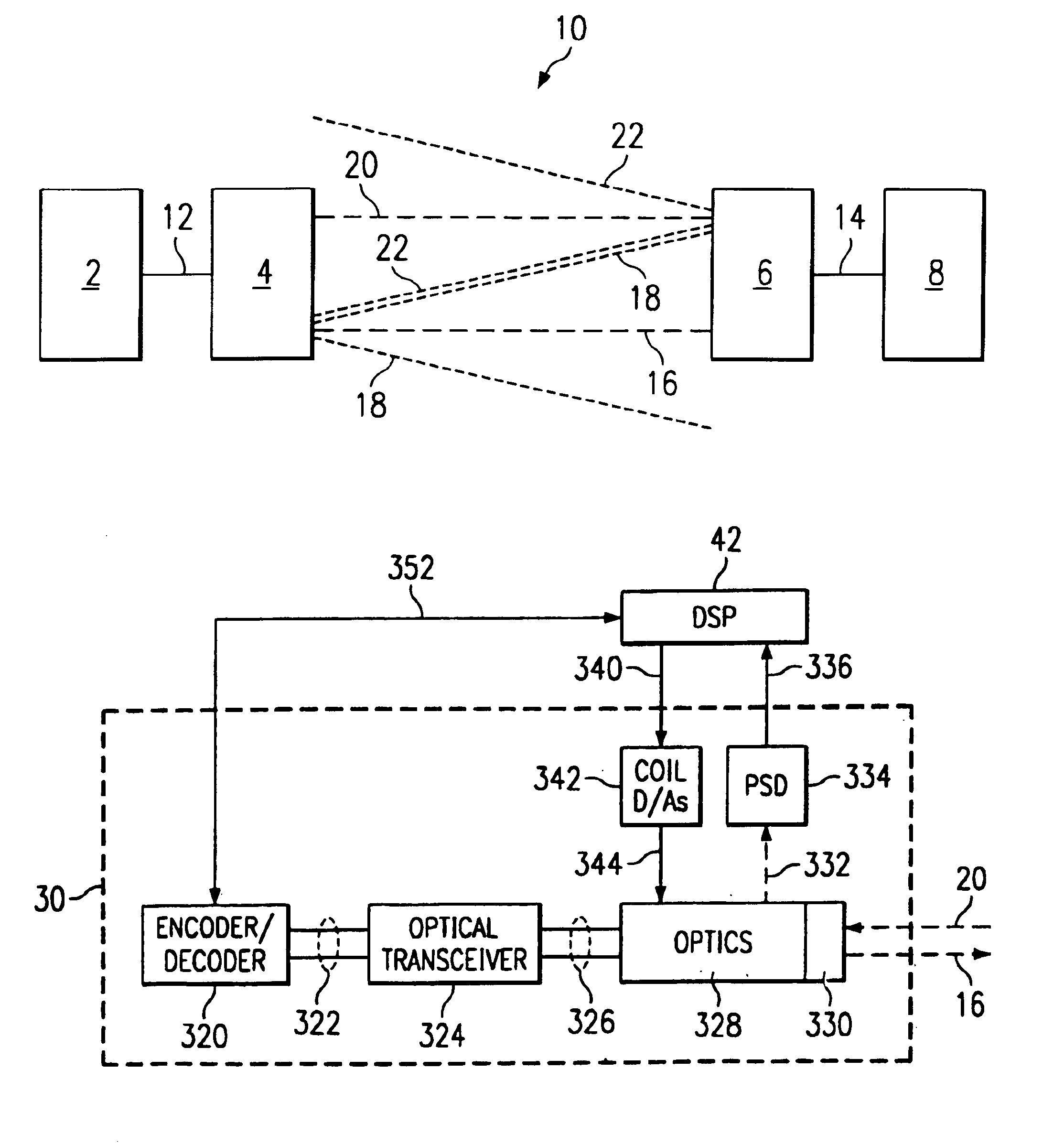
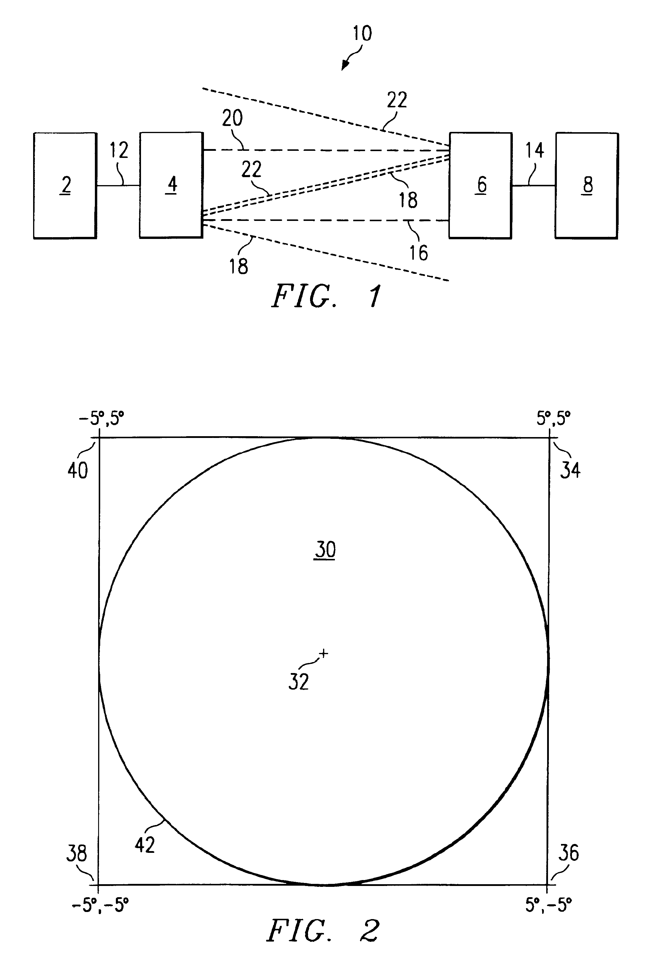
[0034]FIG. 1 illustrates a preferred embodiment optical wireless system 10, including a first data source / sink 2 connected to a first Optical Wireless Link (“OWL”) 4. The OWL 4 can both transmit to and receive data from a second OWL 6 over a wireless optical path. OWL 6 is in turn connected to a second data sink / source 8. Preferably each OWL device is an optical path-to-sight modem. As used herein, the term path-to-sight is intended to mean an unobstructed optical path generally through the ether, as contrasted with through an optic fiber, which path can include reflection. An advantageou...


PUM


Abstract

Optical wireless links automatically align themselves using feedback information that is transmitted over the light beams being aligned. Each link performs an acquisition routine in which its light beam is swept through a pre-defined pattern while transmitting its beam alignment information. When a link receives beam alignment information from a remote link, it updates its transmission to include the alignment information received from the remote link. At some point during the acquisition routine, the remote link will receive its own alignment information “echoed back” from the first link and will re-align its beam accordingly. At some point, each link will have received its own alignment information echoed back from the other link and will have aligned itself to that position. Data communication can begin at that point, or a more refined alignment step can then be performed. The alignment information can be based upon position, sample number, or time transmitted.

Description

CROSS REFERENCE TO RELATED APPLICATION[0001]This Application claims benefit of U.S. Provisional Application No. 60 / 285,461 filed on Apr. 20, 2001 and entitled “Method and Apparatus for Aligning Optical Wireless Link,” which provisional application is hereby incorporated by reference.[0002]The following co-pending, co-assigned patent applications are related to the present invention. Each of the applications is incorporated herein by reference.[0003]Ser. No.Filing DateAttorney Docket09 / 621,385Jul. 21, 2000TI-3071309 / 620,943Jul. 21, 2000TI-3071460 / 234,074Sep. 20, 2000TI-3143760 / 234,086Sep. 20, 2000TI-3143660 / 234,081Sep. 20, 2000TI-3144460 / 233,851Sep. 20, 2000TI-3161260 / 271,936Feb. 26, 2001TI-3267509 / 839,690Apr. 20, 2001TI-3142909 / 923,510Aug. 6, 2001TI-3144060 / 285,460Apr. 20, 2001TI-32926FIELD OF THE INVENTION[0004]This invention relates generally to optical wireless communications, and more specifically, to self-alignment of optical wireless links using positional feedback across the ...

Claims


Application Information

Patent Timeline
Patent Type & Authority Patents(United States)
IPC IPC(8): B81B3/00H04B10/10G02B6/35
CPCB81B3/0062G02B6/3512G02B6/359H04B10/1121H04B10/1123H04B10/1125H04B10/1141
Inventor HEMINGER, MARK DAVIDOETTINGER, ERIC GREGORYHAGEN, MARK DAVIDNORTHRUP, KARL KIRK
Owner TEXAS INSTR INC
Why Eureka
Try Eureka