Catalyst degradation determining method

a technology of catalytic degradation and determining method, which is applied in the direction of process and machine control, electrical control, instruments, etc., can solve the problems of low efficiency of removing unburned co, low efficiency of hc by the oxidizing function of the catalyst, and the likely emission of nitrogen oxides nox, etc., to achieve the effect of delayed replacement time of the upstream-of-catalytic converter air-fuel ratio sensor

Inactive Publication Date: 2005-07-12
TOYOTA JIDOSHA KK
View PDF12 Cites 29 Cited by
  • Summary
  • Abstract
  • Description
  • Claims
  • Application Information

AI Technical Summary

Benefits of technology

[0020]Accordingly, a catalyst degradation determining method capable of minimizing the emission of harmful components, and estimating a maximum oxygen storage amount of a catalyst within a relatively short period of time, and determining whether the catalyst has degraded on the basis of the maximum oxygen storage amount is provided as an embodiment of the invention.

Problems solved by technology

If the upstream-of-catalyst air-fuel ratio is kept rich of the stoichiometric air-fuel ratio immediately after the air-fuel ratio sensor output rich-side switch, unburned components, such as CO, HC and the like, are readily discharged since the oxygen storage amount of the catalyst is “0” and the oxygen releasing function of the catalyst is not effective.
Furthermore, since the oxygen releasing function of the catalyst is not effective and the efficiency of removal of unburned CO, HC by the oxidizing function of the catalyst is low, large amounts of unburned CO and HC are emitted into the atmosphere immediately after the air-fuel ratio sensor output rich-side switch occurs although the upstream-of-catalyst air-fuel ratio immediately following the air-fuel ratio sensor output rich-side switch is set at the stoichiometric air-fuel ratio or an air-fuel ratio lean of the stoichiometric air-fuel ratio.
If the upstream-of-catalyst air-fuel ratio is kept lean of the stoichiometric air-fuel ratio immediately after the air-fuel ratio sensor output lean-side switch occurs, nitrogen oxides NOx are likely to be emitted since the oxygen storage amount of the catalyst has reached the maximum oxygen storage amount and the oxygen storing function of the catalyst is not effective.
Furthermore, since the oxygen storing function of the catalyst is not effective and the efficiency of removal of nitrogen oxides NOx by the reducing function of the catalyst is low, a large amount of nitrogen oxides NOx is emitted into the atmosphere immediately after the air-fuel ratio sensor output lean-side switch occurs although the upstream-of-catalyst air-fuel ratio immediately following the air-fuel ratio sensor output lean-side switch is set at the stoichiometric air-fuel ratio or an air-fuel ratio that is rich of the stoichiometric air-fuel ratio.
Therefore, if the maximum oxygen storage amount of the catalyst is estimated by the rich air-fuel ratio-based estimation method or the lean air-fuel ratio-based estimation method while using the assumption that the window range is constant, and that the predetermined rich air-fuel ratio is a constant air-fuel ratio which is within the window range and near the lower limit value of the window range, or that the predetermined lean air-fuel ratio is a constant air-fuel ratio which is within the window range and near the upper limit value of the window range, the following problem may occur.
However, this measure creates a problem of a prolonged time elapsing from the beginning of control of the upstream-of-catalyst air-fuel ratio to the predetermined rich air-fuel ratio or lean air-fuel ratio to the switch of the output of the downstream-of-catalyst air-fuel ratio sensor (i.e., a prolonged period results for calculation of the maximum oxygen storage amount of the catalyst).

Method used


Image

  • Catalyst degradation determining method
  • Catalyst degradation determining method
  • Catalyst degradation determining method

Examples


Embodiment Construction

[0072]In the following description and the accompanying drawings, the present invention will be described in more detail with reference to exemplary embodiments.

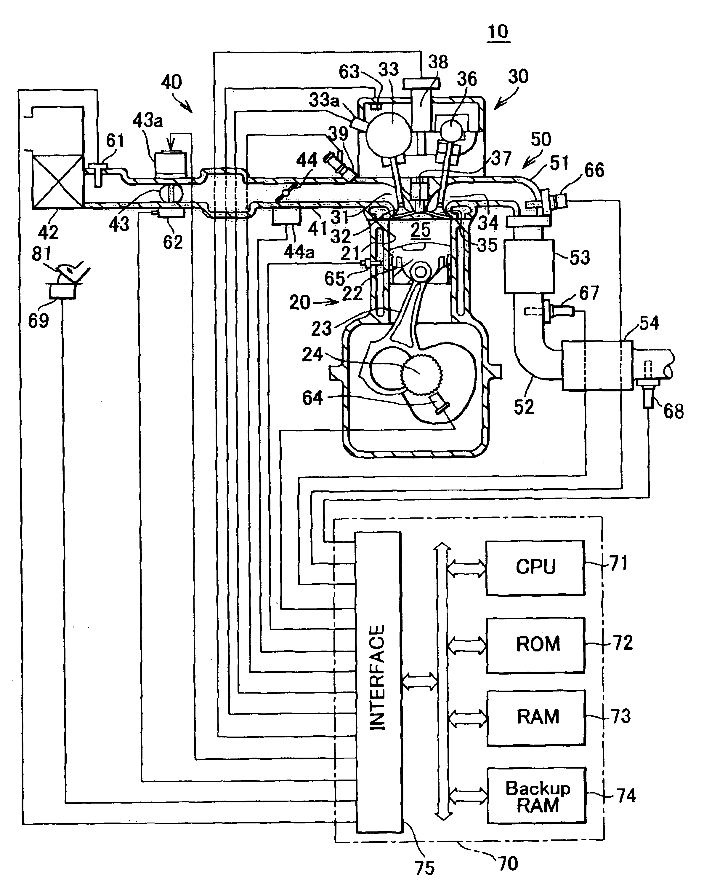
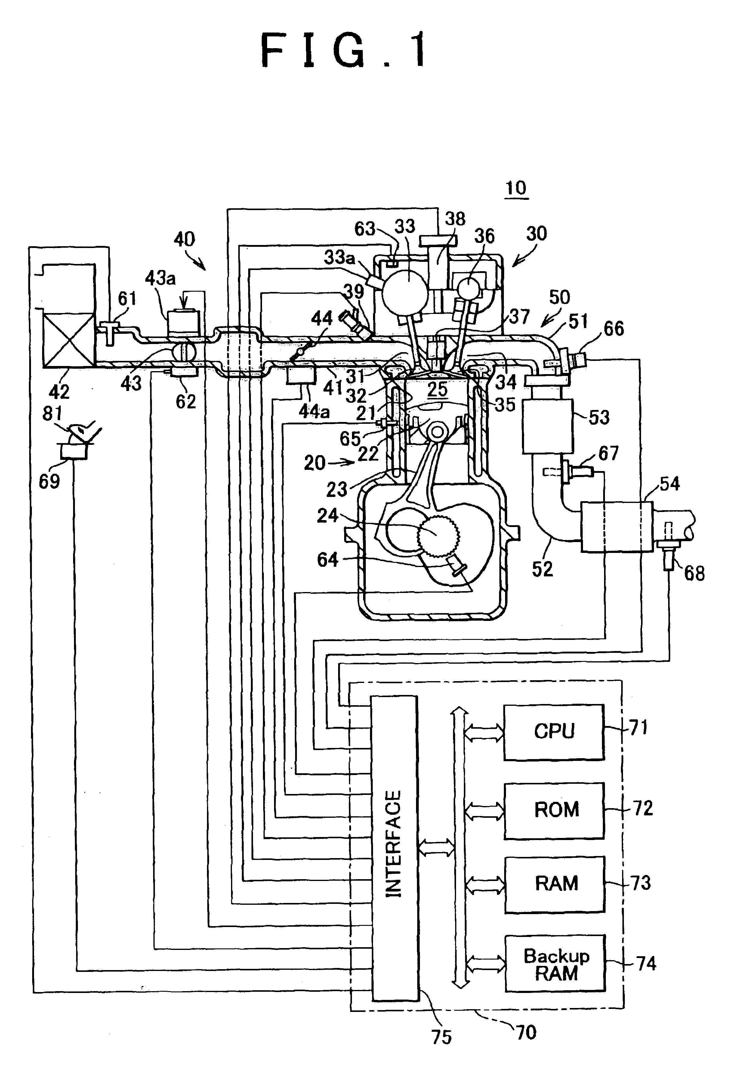
[0073]FIG. 1 is a schematic illustration of the construction of a system in which an emission control apparatus (catalyst degradation determining apparatus) for carrying out a catalyst degradation determining method in accordance with an embodiment of the invention is applied to a spark ignition type multi-cylinder (e.g., four-cylinder) internal combustion engine 10.

[0074]The internal combustion engine 10 includes a cylinder block section 20 that includes a cylinder block lower case, an oil pan, etc., a cylinder head section 30 fixed to the cylinder block section 20, an intake system 40 for supplying gasoline mixture to the cylinder block section 20, and an exhaust system 50 for releasing exhaust gas from the cylinder block section 20 to the outside.

[0075]The cylinder block section 20 includes cylinders 21, pistons 22, conne...


PUM


Abstract

A catalyst degradation determining method includes the steps of: controlling an upstream-of-catalyst air-fuel ratio occurring upstream of a first catalyst to an air-fuel ratio that is rich of a stoichiometric air-fuel ratio so that first and second catalysts store oxygen up to a maximum storage amount of oxygen. The method then includes the steps of controlling the upstream-of-catalyst air-fuel ratio to a first lean air-fuel ratio until an output of a downstream-of-first-catalyst sensor indicates a lean air-fuel ratio, and then to a second lean air-fuel ratio and that has a value that is determined in accordance with an oxidizing-reducing capability index value, until a time point when an output of a downstream-of-second-catalyst air-fuel ratio sensor indicates an air-fuel ratio that is lean.

Description

INCORPORATION BY REFERENCE[0001]The disclosure of Japanese Patent Application No. 2002-201544 filed on Jul. 10, 2002, including the specification, drawings and abstract is incorporated herein by reference in its entirety.BACKGROUND OF THE INVENTION[0002]1. Field of Invention[0003]The invention relates to a catalyst degradation determining method for determining whether a catalyst disposed in an exhaust passage of an internal combustion engine has degraded.[0004]2. Description of Related Art[0005]A known three-way catalyst (in this specification, sometimes referred to simply as “catalyst”) for controlling exhaust gas from an internal combustion engine is disposed in an exhaust passage of the internal combustion engine. The three-way catalyst performs the function of oxidizing unburned components (HC, CO) (oxidizing function), and the function of reducing nitrogen oxides (NOx) (reducing function), and is able to substantially remove harmful components, including unburned components an...

Claims


Application Information

Patent Timeline
Patent Type & Authority Patents(United States)
IPC IPC(8): F01N11/00F01N7/00F01N7/02F02D45/00F01N3/00F01N3/20F01N3/24F02D41/14
CPCF01N3/101F01N11/00F01N11/007F01N13/0093F01N13/009F01N2550/02F02D2200/0816Y02T10/47Y02T10/22Y02T10/12Y02T10/40
Inventor KAMOTO, AKIRANAGAI, TOSHINARIOI, YASUHIROADACHI, NORIYASUIDE, KOJIKOBAYASHI, DAISUKEOKAZAKI, SHUNTAROKATO, NAOTOUCHIDA, TAKAHIRO
Owner TOYOTA JIDOSHA KK
Why Eureka
Try Eureka