Engine cooling device and engine cooling method

a cooling device and engine technology, applied in the direction of engine starters, machines/engines, electric control, etc., can solve the problems of restricted recalculation of low-temperature cooling mediums to the body of the engine, and achieve the effect of reducing the flow resistance of cooling mediums, increasing the heat-accumulating circuit, and suitably promoting engine warm-up

Inactive Publication Date: 2005-07-12
TOYOTA JIDOSHA KK
View PDF11 Cites 8 Cited by
  • Summary
  • Abstract
  • Description
  • Claims
  • Application Information

AI Technical Summary

Benefits of technology

[0017]According to the aforementioned cooling device and the aforementioned cooling method, when cooling medium in the heat-accumulating container is supplied to the body of the engine, the flow resistance of cooling medium is reduced through an increase in the flow rate of the cooling medium flowing through the bypass passage. Therefore, the flow rate of cooling medium flowing through the cooling circuit and the heat-accumulating circuit is increased. Because the cooling medium in the heat-accumulating container is thereby supplied to the body of the engine at an early stage, the warm-up of the engine can be promoted suitably. After the cooling medium in the heat-accumulating container has been supplied to the body of the engine, the heat-accumulating passage is disconnected from the cooling circuit and the control valve is closed. Therefore, the recalculation of low-temperature cooling medium to the body of the engine is restricted. Thereby, the temperature of the body of the engine can be suitably restrained from falling due to the low-temperature cooling medium.

Problems solved by technology

Therefore, the recalculation of low-temperature cooling medium to the body of the engine is restricted.

Method used


Image

  • Engine cooling device and engine cooling method
  • Engine cooling device and engine cooling method
  • Engine cooling device and engine cooling method

Examples


Embodiment Construction

[0031]In the following description, the invention will be described in more detail in terms of exemplary embodiments.

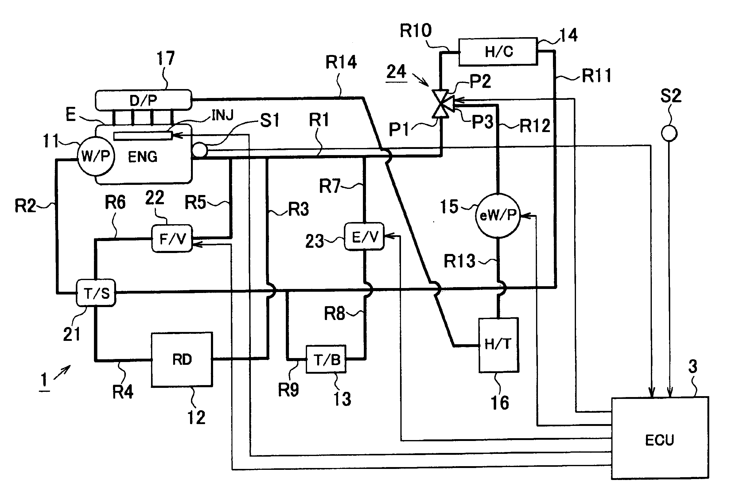
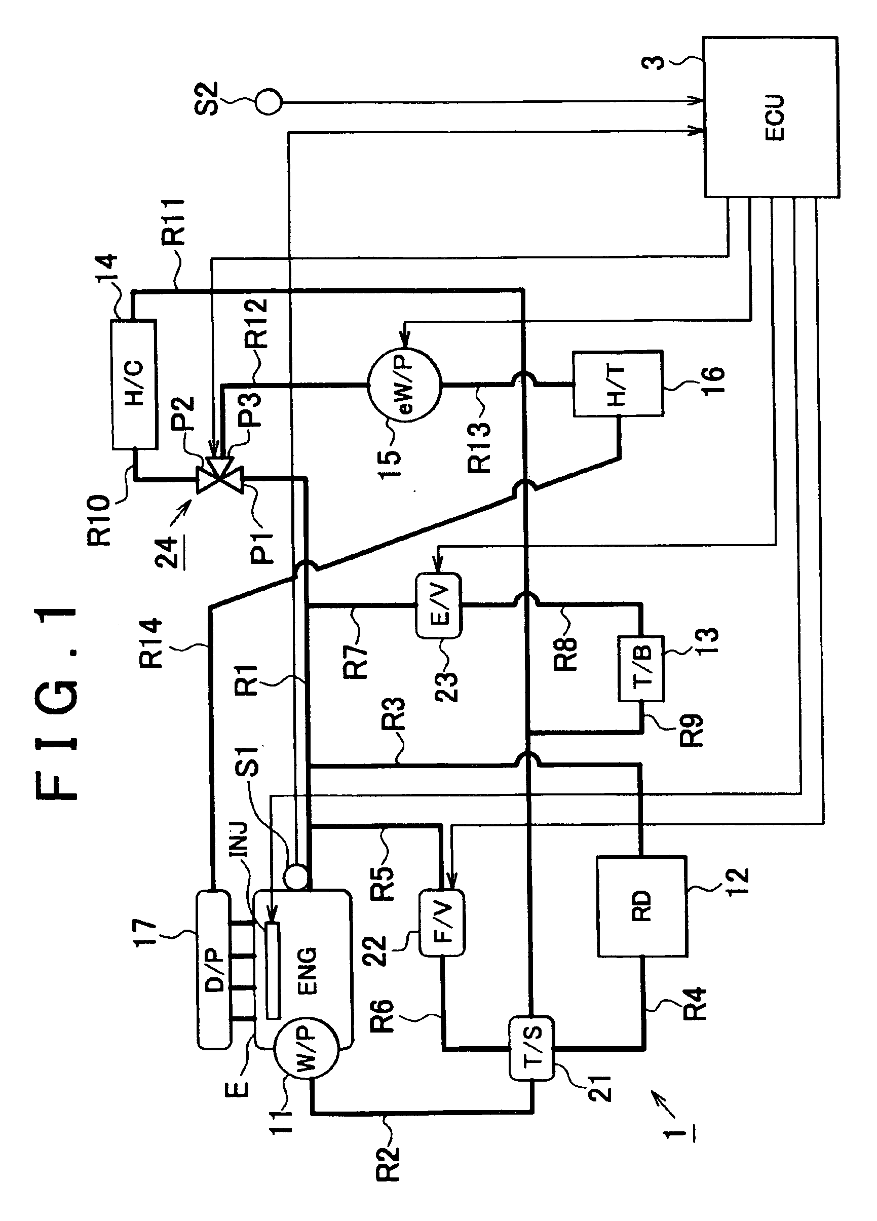
[0032]The overall construction of an engine cooling device having a function of cooling an engine E (engine body) is illustrated in FIG. 1.

[0033]First of all, the functions of various components of the engine cooling device 1 will be described. A water pump 11 is driven through the engine E and force-feeds coolant.

[0034]A radiator 12 exchanges heat between coolant and outside air.

[0035]A throttle body 13 contains a throttle valve and adjusts the amount of intake air in accordance with the opening of the valve.

[0036]A heater core 14 exchanges heat between coolant and air for heating the interior of a vehicle compartment. The heat-exchanged air is supplied to the interior of the vehicle compartment through a heater.

[0037]An electric water pump 15 is driven through a battery and force-feeds coolant.

[0038]A heat-accumulating container 16 stores coolant and thermally insul...


PUM


Abstract

The invention provides an engine cooling device capable of suitably promoting the warm-up of an engine. This engine cooling device comprises a cooling circuit and a heat-accumulating passage. The cooling circuit is composed of a radiator passage, a bypass passage, and a flow rate control value for controlling the flow rate of coolant flowing though the bypass passage. The heat-accumulating passage is provided with a heat-accumulating container, and constitutes a heat-accumulating circuit for causing coolant in the heat-accumulating container to circulate via the engine. The cooling device completes the heat-accumulating circuit by connecting the heat-accumulating passage to the cooling circuit to supply the cooling medium in the heat-accumulating container to the body of the engine, opens the flow rate control valve to increase a flow rate of cooling medium flowing though the bypass passage, then disconnects the heat-accumulating passage from the cooling circuit, and closes the flow rate control valve.

Description

INCORPORATION BY REFERENCE[0001]The disclosure of Japanese Patent Application No. 2003-096645 filed on Mar. 31, 2003 including the specification, drawings and abstract is incorporated herein by reference in its entirety.BACKGROUND OF THE INVENTION[0002]1. Field of Invention[0003]The invention relates to an engine cooling device / method designed to cool an engine through circulation of cooling medium.[0004]2. Description of Related Art[0005]As an engine cooling device designed to cool an engine through circulation of cooling medium, a cooling device equipped with a heat-accumulating container has been known. A cooling device of this type causes cooling medium that has reached a high temperature by receiving heat from an engine to flow into a heat-accumulating container, and thereby makes it possible to thermally insulate and store the cooling medium.[0006]As an engine cooling device equipped with a heat-accumulating container, there is known a device that is disclosed in Japanese Pate...

Claims


Application Information

Patent Timeline
Patent Type & Authority Patents(United States)
IPC IPC(8): F01P11/20F01P11/14F02N17/00F01P7/16F02N17/06F01P7/14F01P3/20F02D43/00F02D41/06F02N19/10
CPCF01P7/162F01P7/165F01P11/20F02N19/10F01P2011/205F01P2060/08
Inventor ARISAWA, KATUHIKOYOSHIKAWA, SHIGETAKASHINPO, YOSHIKAZU
Owner TOYOTA JIDOSHA KK
Why Eureka
Try Eureka