Chemical feeder

Inactive Publication Date: 2005-07-12
INNOVATIVE WATER CARE LLC
View PDF18 Cites 14 Cited by
  • Summary
  • Abstract
  • Description
  • Claims
  • Application Information

AI Technical Summary

Benefits of technology

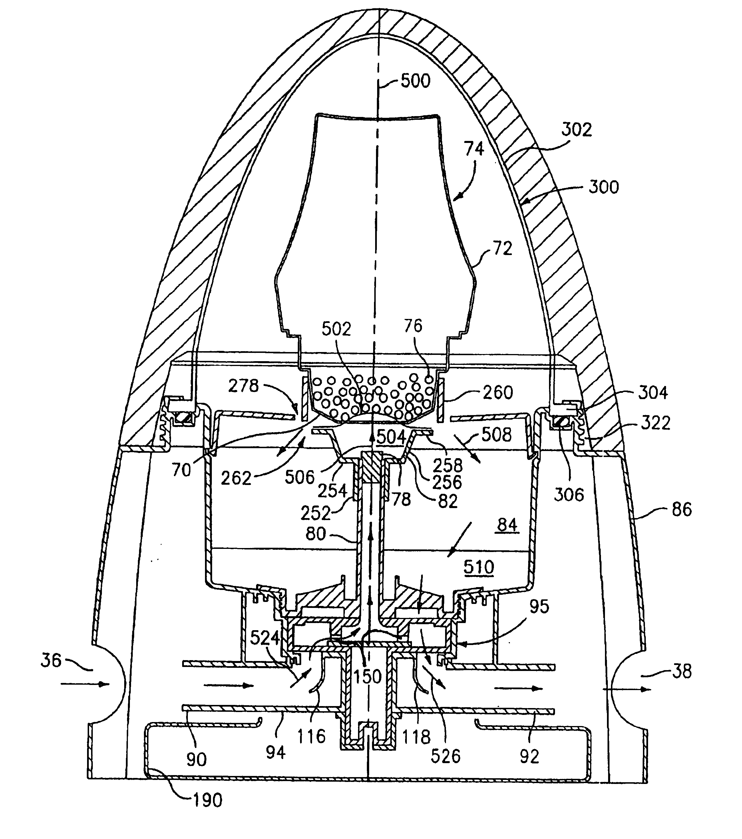
[0009]One aspect of the present invention is directed to a feeder device for introducing a chemical into a flow of water comprising: a feeder inlet and a feeder outlet; a reservoir of the chemical in solid form and having a foraminate lower portion; a first conduit having an outlet and in communication with the feeder inlet in at least a first feeder condition, maintaining a body of water in which said conduit outlet is immersed; and an outlet chamber which in at least said first feeder condition receives overflow containing the dissolved chemical from the body and is in communication with the feeder outlet.

Problems solved by technology

Obtaining proper dissolution of the treatment chemical and avoiding undesirable deposits or residues have posed problems in feeder design.
Particular problems exist with the use of commercial calcium hypochlorite pellets which produce calcium carbonate deposits.

Method used


Image

  • Chemical feeder
  • Chemical feeder
  • Chemical feeder

Examples


Embodiment Construction

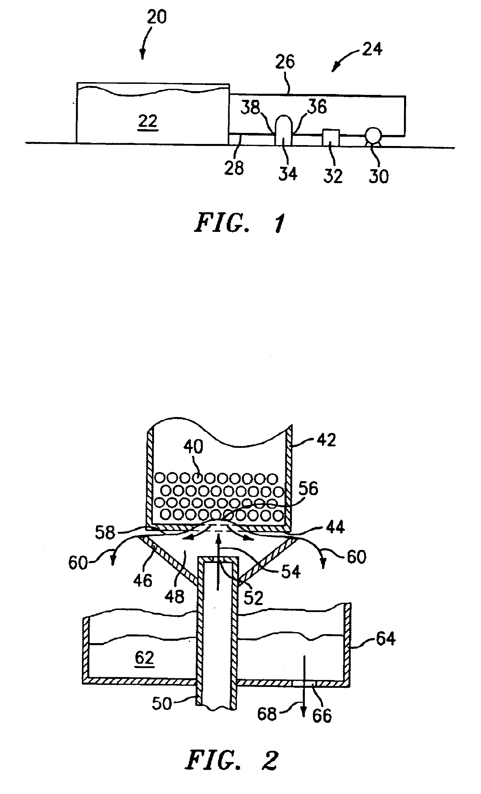
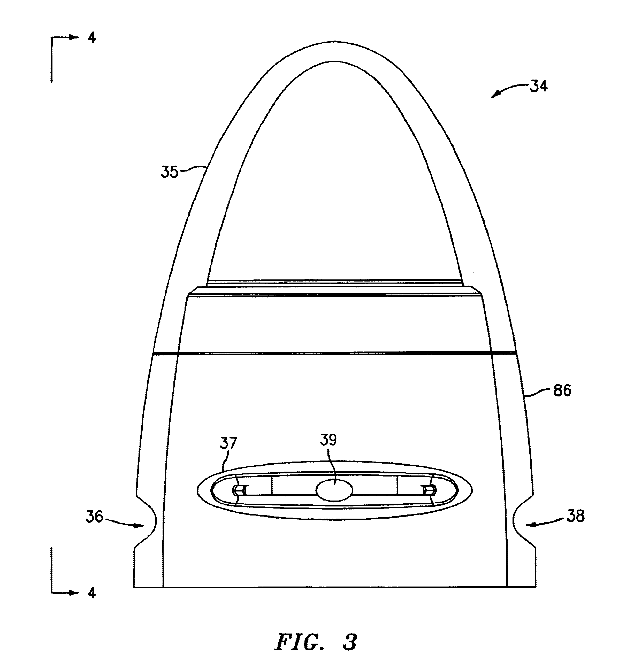
[0039]FIG. 1 shows a pool 20 containing a body 22 of pool water and associated with a circulation system 24. The exemplary pool is of the above-ground type although this should not be regarded as limiting. The circulation system has a pool outlet conduit 26 drawing water from the pool and a pool return conduit 28 returning water to the pool. Flow through these conduits is induced by a pump 30 with a low pressure (suction) side toward the pool outlet conduit and a high pressure side toward the pool return conduit. Downstream of the pump, there may be a system filter 32 filtering debris and the like from water flowing from the pump and a feeder or chlorinator 34 introducing chlorine to the flow. The feeder has an inlet and an outlet respectively shown as 36 and 38. Alternatively, a manifold may be used in line instead of feeder 34. In that case, a feeder or chlorinator 34 would be connected to the manifold in an off-line fashion.

[0040]FIG. 2 semi-schematically shows an example of cert...


PUM

PropertyMeasurementUnit
pressureaaaaaaaaaa
pressureaaaaaaaaaa
heightaaaaaaaaaa

Abstract

A feeder that uses a local elevation or stationary wave of a body of water to facilitate the dissolving of a chlorine-containing water treatment chemical.

Description

CROSS-REFERENCE TO RELATED APPLICATION[0001]This patent application relates to the subject matter of U.S. Provisional Patent Application Ser. No. 60 / 338,386 entitled “Chemical Feeder” that was filed on Dec. 4, 2001, and U.S. Provisional Patent Application Ser. No. 60 / 392,727 entitled “Chemical Feeder” that was filed on Jun. 27, 2002. The disclosures of both of these U.S. Provisional Applications are incorporated by reference in its entirety herein as if set forth at length.BACKGROUND OF THE INVENTION[0002](1) Field of the Invention[0003]This invention relates to water treatment, and more particularly to feeders for introducing treatment chemicals into a recirculating water stream from a swimming pool or the like.[0004](2) Brief Description of the Art[0005]If untreated, swimming pool water provides an hospitable forum for the growth of bacteria, algae, and other undesirable and potentially unhealthful organisms. It, accordingly, has become common practice to treat pool water on both ...

Claims


Application Information

Patent Timeline
Patent Type & Authority Patents(United States)
IPC IPC(8): B01F1/00C02F1/68E04H4/12E04H4/00B01D37/00B01D37/02C02F1/76B01DC02F1/50B01F15/02
CPCB01F1/0033C02F1/688E04H4/1281B01D37/025C02F1/001Y02E60/36C02F2103/42C02F2209/40C02F2301/046C02F1/76Y10T137/4891Y10T137/0318B01F21/221
Inventor BLANCHETTE, DAVID W.ZETENA, CHRISTOPHER M.PALOIAN, MICHAELORCHARD, ANTHONY R.
Owner INNOVATIVE WATER CARE LLC
Why Eureka
Try Eureka