Drill

a drill bit and tip technology, applied in the field of drill bit, can solve the problems of increasing the driving torque applied to the drill bit for drilling, the chip produced by the thinning cutting edge tends to clog, and the drill bit wear is rapid, so as to improve the wear resistance of the tip portion

Inactive Publication Date: 2005-07-12
MITSUBISHI MATERIALS CORP
View PDF15 Cites 42 Cited by
  • Summary
  • Abstract
  • Description
  • Claims
  • Application Information

AI Technical Summary

Benefits of technology

[0037]In the drill according to all of above aspects, a hard coating such as TiN, TiCN, TiAIN, etc. may be preferably coated on the surface of

Problems solved by technology

In addition, because the chips which are produced by the cutting edge and flow to the chamfer of the wall of the chip discharge flute or to outside the V-shape tend to move out of the drill, the curling performance of the chips are generally degraded and non-curled chips are strongly pressed against the trailing wall surface of the chip discharge flute, which applies a great frictional resistance to the drill main body, which leads to rapid wear of the drill and to increase in a driving torque applied to the drill for drilling.
Hei 4-46690, in which the thinning portion is formed by simply cutting the end portion of the wall of the chip discharge flute to define a V-shaped recess, the chips produced by the thinning cutting edge tend to clog at the bottom of the V-shaped recess, and even to cause fusion since the chips are clogged and not cooled, specifically under high speed and dry drilling conditions.
On the other hand, when the oblique angle of the bottom is large, the tip angle of the drill main body measured in cross section alon

Method used


Image

  • Drill
  • Drill
  • Drill

Examples


first embodiment

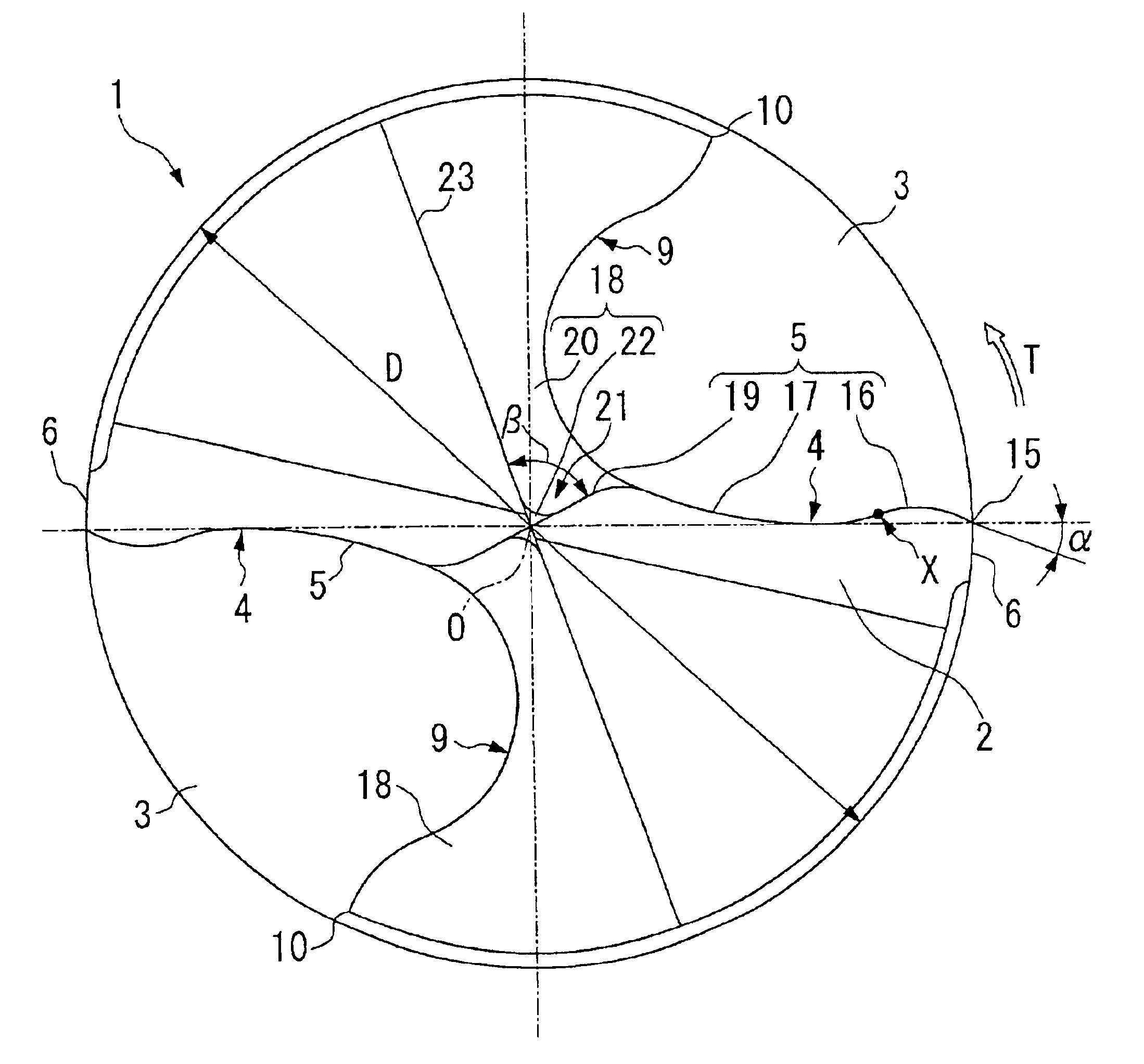
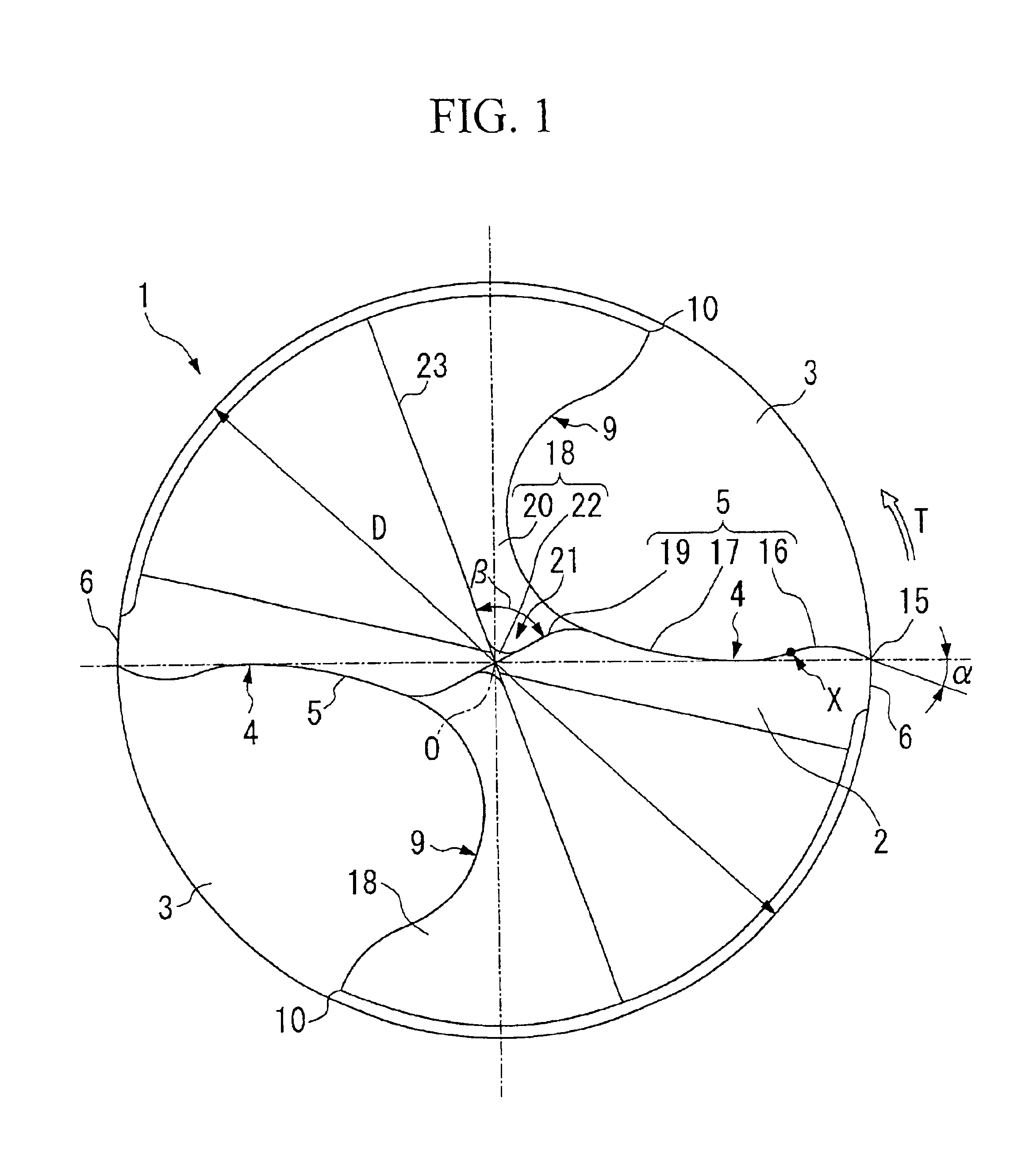
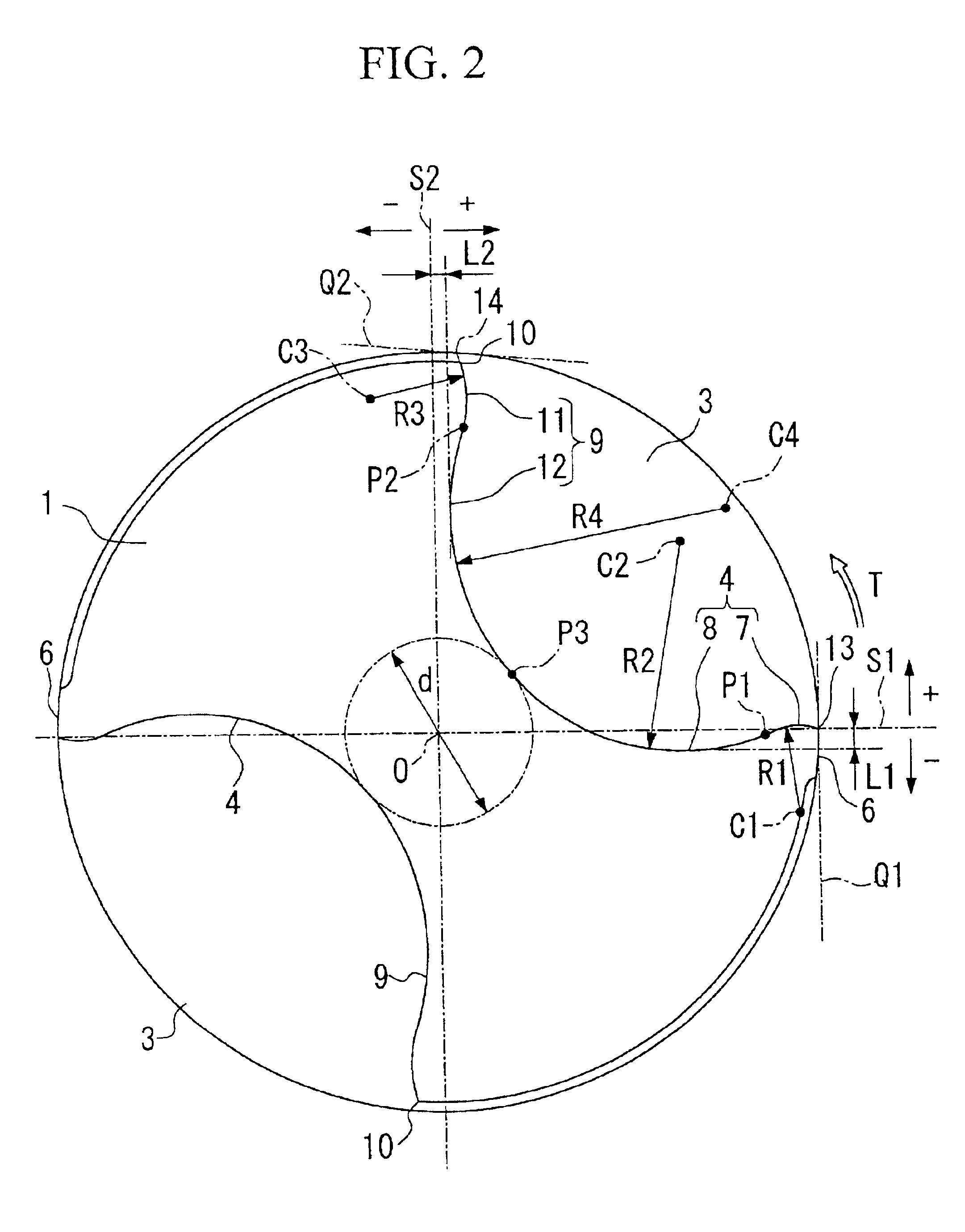
[0054]FIGS. 1 to 12 show the present invention. In this embodiment, the drill main body 1 made of a hard material, such as cemented carbide, or the like, is substantially formed in a cylindrical shape with the axis of rotation O as a center, in which a pair of chip discharge flutes 3 are symmetrically formed with respect to the axis of rotation O from the tip flank 2 toward the shank of the drill main body 1 while being twisted at a constant twist ratio in the direction opposite to the direction of drill rotation during use. A pair of cutting edges 5 are formed along intersecting ridges where wall surfaces 4 of the chip discharge flutes 3 facing in the direction of rotation T intersects the tip flank 2. The periphery, the tip flank 2, and the chip discharge flute 3 on the drill main body for drilling are covered with a hard coating, such as TiN, TiCN, TiAl, or the like.

[0055]The wall surface 4 comprises a first convex surface 7 located near the periphery, intersecting with a margin ...

second embodiment

[0104]the present invention will be explained below with reference to FIGS. 13 to 15. As shown in FIG. 13, the wall surface 104 comprises a first convex surface 107 located near the periphery, intersecting with a margin portion 106, and seen as a convex line protruding in the direction of rotation when viewed in cross section perpendicular to the axis of rotation O′ as shown in FIG. 14, and a first concave surface 108 located inside the first convex surface 107 and seen as a concave line when viewed in the above-mentioned cross section. The convex line corresponding to the first convex surface 107 is smoothly connected to the concave line corresponding to the first concave surface 108 at a point of contact P1′. In this embodiment, the wall surfaces 109 of the chip discharge flutes 103 facing in the direction opposite to the direction of drill rotation T′ comprises a second convex surface 111 located near the periphery, extending to a heel portion 110, and seen as a convex line protr...


PUM

PropertyMeasurementUnit
Fractionaaaaaaaaaa
Fractionaaaaaaaaaa
Fractionaaaaaaaaaa

Abstract

The present invention provides a drill comprising: a drill main body rotatable about an axis of rotation, and having a tip end with a tip flank and a shank; a chip discharge flute formed on a periphery of the drill main body, and extending from the tip end toward the shank of the drill main body; and a cutting edge formed along an intersecting ridge where a wall surface of the chip discharge flute facing in the direction of drill rotation intersects the tip flank of the drill main body, wherein the cutting edge comprises a convex cutting edge toward the periphery and a concave cutting edge smoothly extending from the convex cutting edge. When drilling work is performed with this drill, the chips are generally curled and can be smoothly discharged without being excessively abutted against the wall surface of the chip discharge flute; consequently, the chips can be smoothly discharged, and the drill main body is subjected to less frictional resistance, which leads to less wear on the drill and less driving torque for drilling. Therefore, the drill life can be preferably extended even under severe drilling conditions, such as during high speed drilling, and smooth and stable drilling can be performed.

Description

BACKGROUND OF THE INVENTION[0001]1. Field of the Invention[0002]This invention relates to a drill which enables performance of smooth and stable drilling even under severe conditions, specifically, such as high speed and dry drilling.[0003]2. Background Art[0004]A drill designed to be suitable for use under severe drilling conditions in which no or small amounts of cutting lubricant is used is disclosed, for example, in Japanese Unexamined Patent Application, First Publication, No. 2000-198011. The drill disclosed in the above Publication comprises: a center cutting edge extending from a chisel at the tip of a drill main body; a major cutting edge extending outward from the end of the center cutting edge; an outer corner cutting edge obliquely extending in the direction opposite to the direction of drill rotation from the end of the major cutting edge at a certain radius of rotation; and a leading edge consisting of a chip discharge flute and a margin portion, wherein a straight or ...

Claims


Application Information

Patent Timeline
IPC IPC(8): B23B51/02
CPCB23B51/02B23B2251/082Y10T408/909Y10T408/9097B23B2251/14
Inventor YANAGIDA, KAZUYATAKIGUCHI, SHOJISUZUKI, KATSUYUKIINOUE, TAKESHI
Owner MITSUBISHI MATERIALS CORP
Why Eureka
Try Eureka