

Radial piston pump
- Summary
- Abstract
- Description
- Claims
- Application Information
AI Technical Summary
Benefits of technology
Problems solved by technology
Method used
Image

Examples
Embodiment Construction
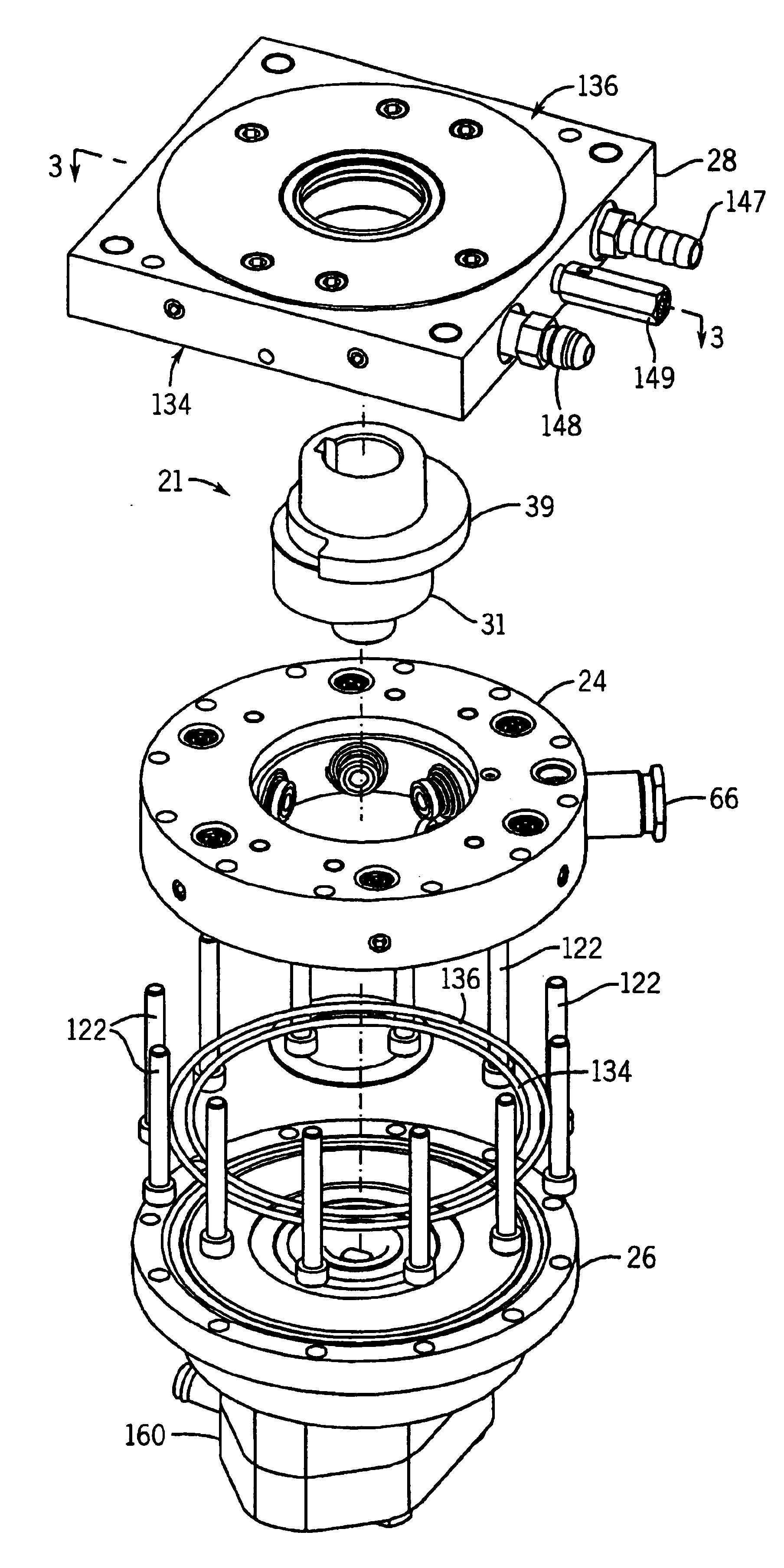
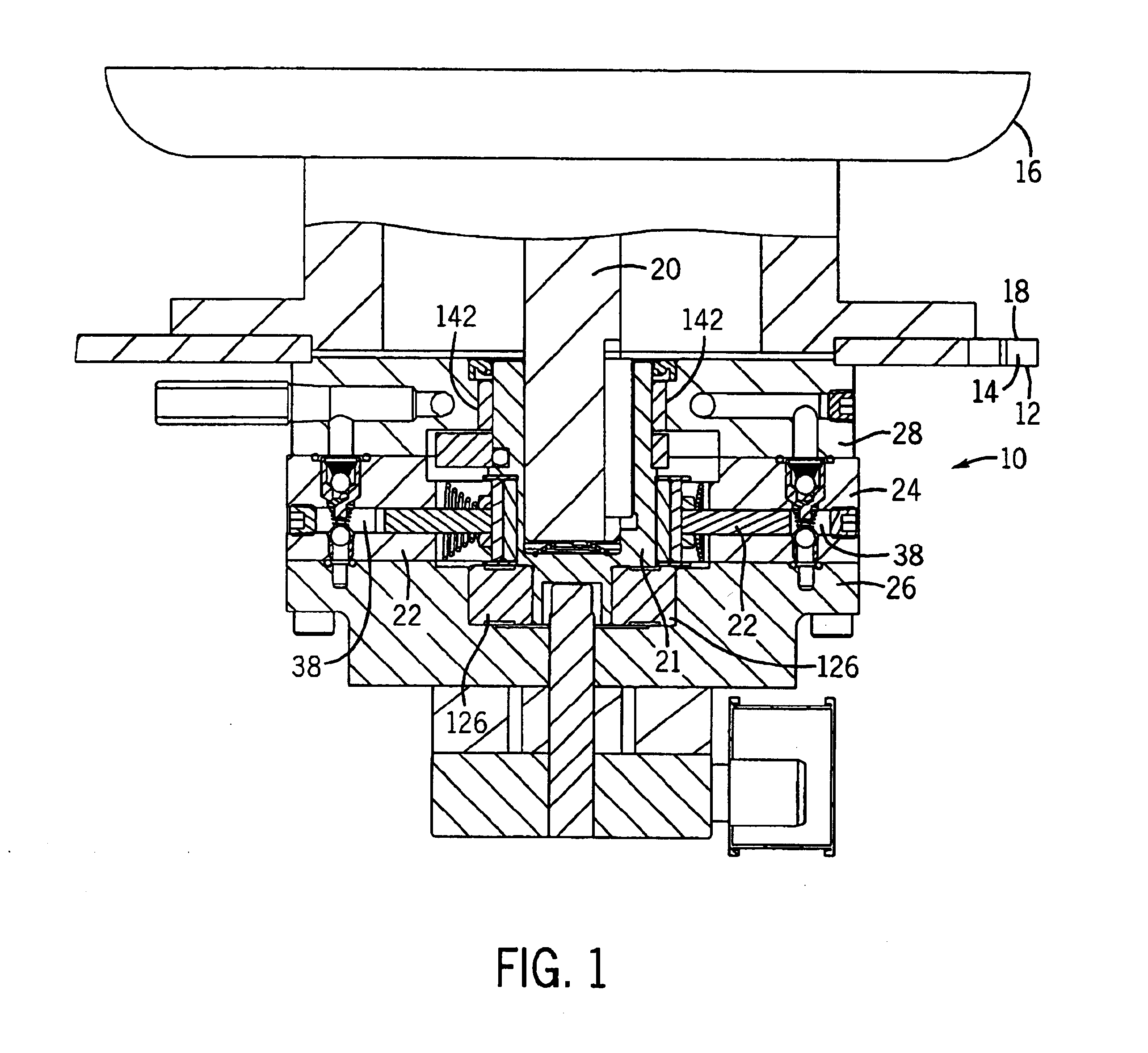
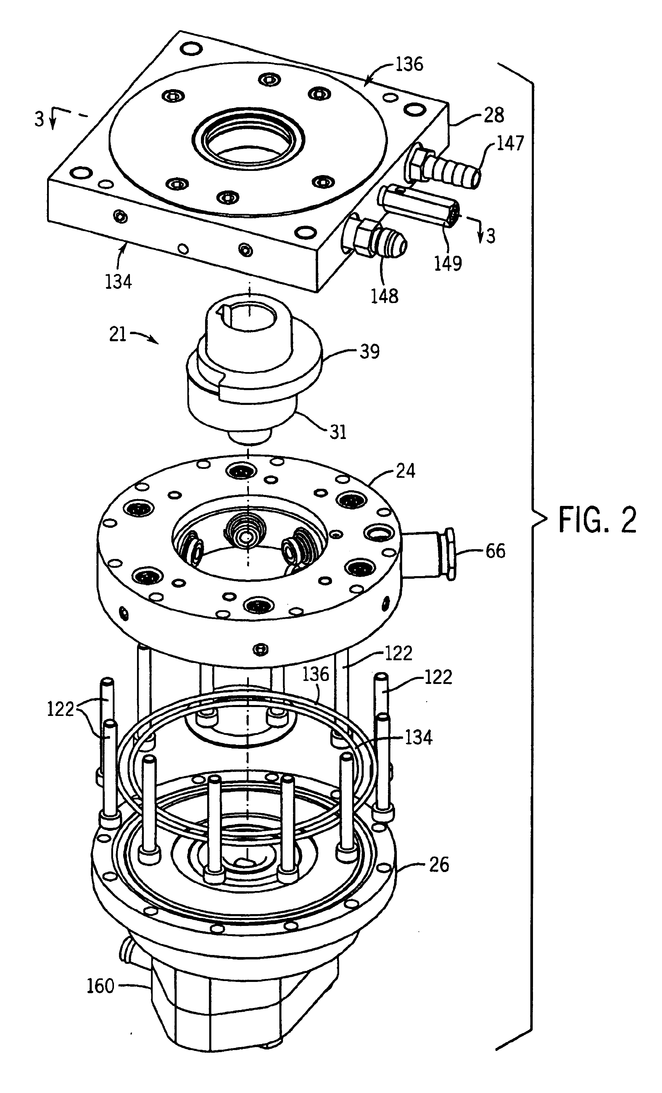
[0026]A radial piston pump 10, shown in FIGS. 1-11, includes a piston ring 24 sandwiched between an intake manifold 26 and an exhaust manifold 28, and is submerged in a fluid, such as oil, hydraulic fluid, and the like. The pump 10 is fixed to one side 12 of a cover plate 14, and is driven by an electric motor 16 fixed to an opposing side 18 of the plate 14. The plate 14 covers an opening formed in a reservoir containing the fluid.
[0027]The electric motor 16 has a rotatable shaft 20 that extends through the plate 14 to rotatably drive pistons 22 reciprocatively received in cylinders 38 formed in the piston ring 24. The motor 16 can be any device having a rotating shaft, such as an electric motor, combustion engine, air powered, and the like. In the embodiment shown in FIGS. 1-11, the motor shaft 20 is concentric with the center of the piston ring 24, and rotatably drives an eccentric rotor 21. A counterbalance 39 fixed to the eccentric rotor 21, such as by a press fit, minimizes vib...
PUM
 Abstract
Description
Claims
Application Information