Device and method for bicompartmental arthroplasty

a technology of bicompartmental arthroplasty and a device, applied in the field of devices and methods for bicompartmental arthroplasty, can solve the problems of sacrifice and achieve the effect of preserving the integrity of anterior and posterior cruciate ligaments

Inactive Publication Date: 2005-07-12
ROLSTON LINDSEY R
View PDF19 Cites 245 Cited by
  • Summary
  • Abstract
  • Description
  • Claims
  • Application Information

AI Technical Summary

Benefits of technology

[0005]A method of performing bicompartmental arthroplasty of a patellofemoral and one other compartment of a patient's knee comprises the steps of making an incision along the anterior aspect of the one other compartment of the knee, excising the remnants of the meniscus of the one other compartment, surgically preparing a proximal end of the one other compartment of the patient's tibia to receive a tibial prosthesis component in a manner so as to preserve the integrity of the anterior and posterior cruciate ligaments. The tibial prosthesis component has a first surface configured to be secured to the surgically prepared one other compartment of the proximal end of the tibia and a second concave curved surface. Next the patella is rotated approximately 90 degrees. The distal end of the one other compartment of a the patient's femur is surgically prepared to receive a femoral prosthesis component. The femoral prosthesis component has a concave trochlea surface and a first surface configured to be secured to the surgically prepared one other compartment of the distal end of the femur. The femoral component also has a second convex curved surface configured to replicate the condyle and articulate with the second concave curved surface of the tibial prosthesis component to permit pivotal articulation between the femoral prosthesis component and the tibial prosthesis component in a manner approximating the articulation of a healthy knee joint. The femoral component is next secured to the femur and the tibial component is secured to the tibia. The patella is positioned over the concave trochlea surface of the femoral prosthesis component and the incision is closed.

Problems solved by technology

Unfortunately total knee replacement results in sacrifice of the anterior and posterior cruciate ligaments.

Method used


Image

  • Device and method for bicompartmental arthroplasty
  • Device and method for bicompartmental arthroplasty
  • Device and method for bicompartmental arthroplasty

Examples


Embodiment Construction

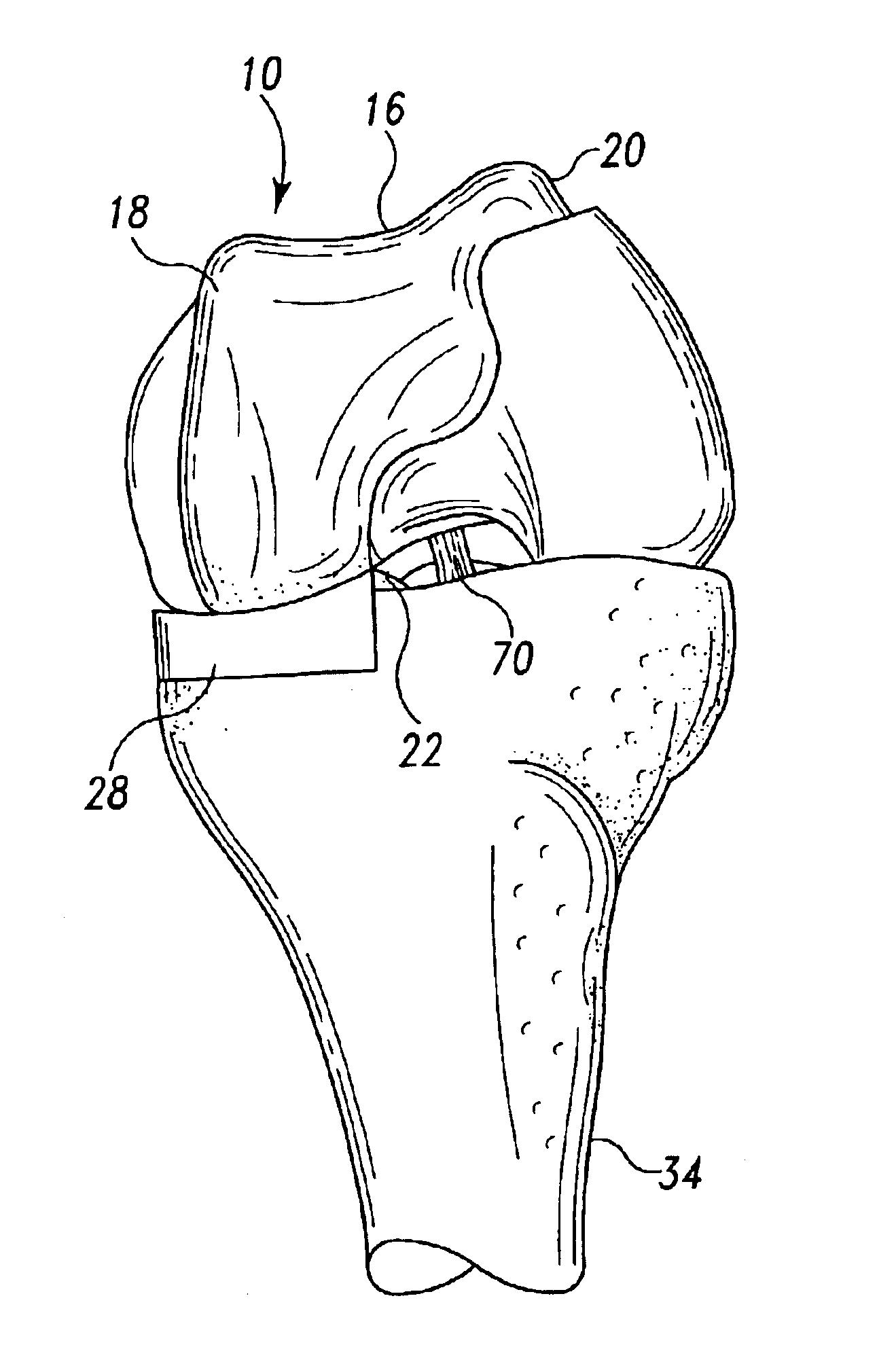
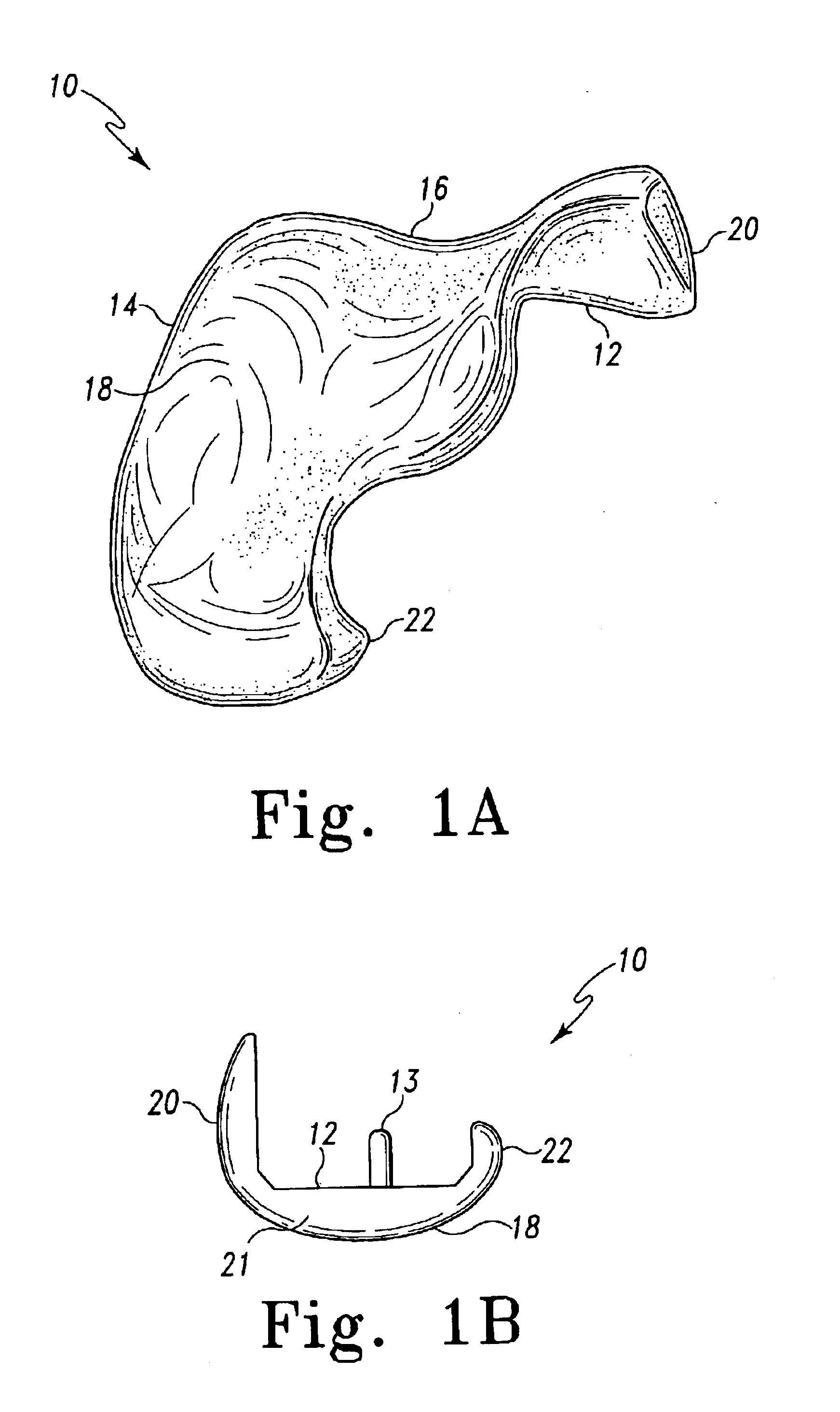
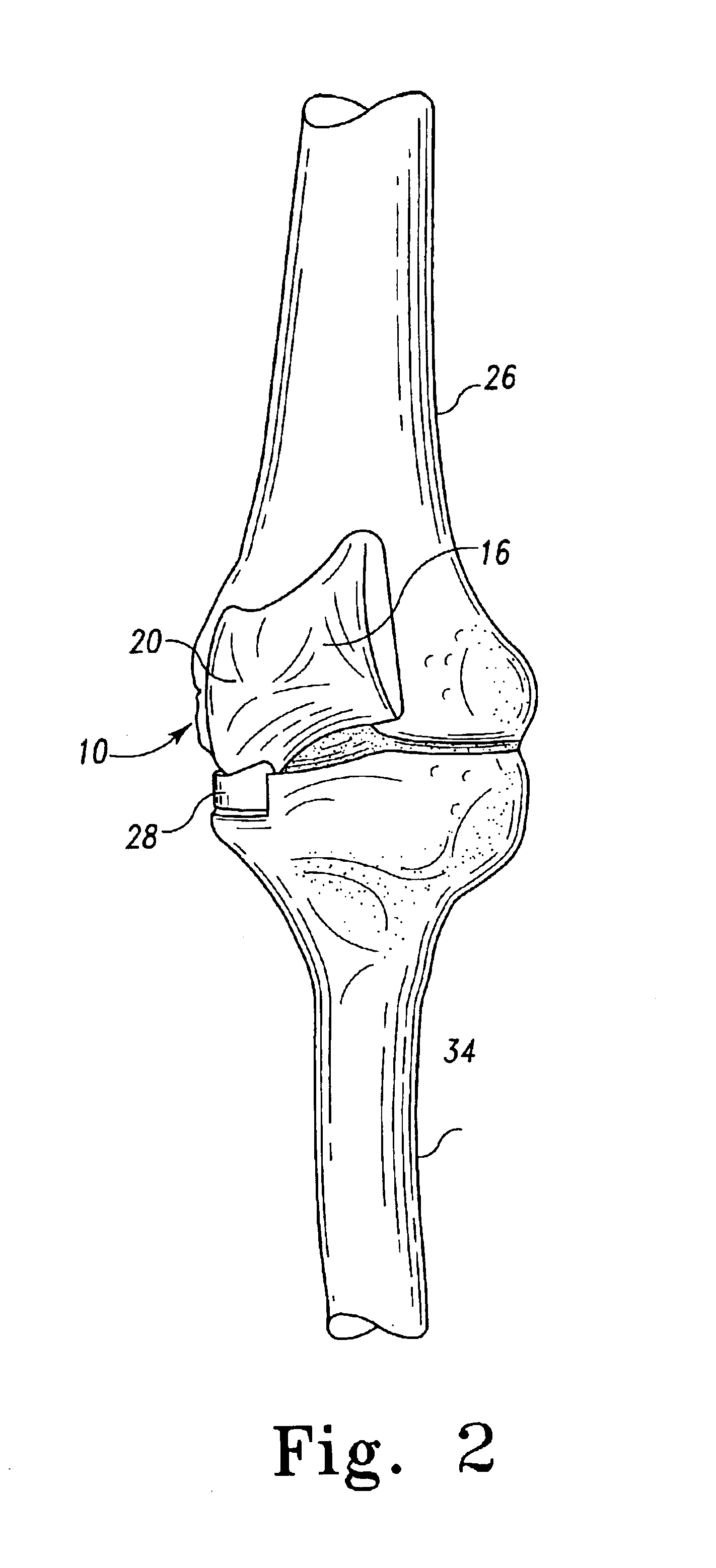
[0021]FIGS. 1A and B illustrate a medial femoral prosthesis component 10 for use in connection with a combination device for bicompartmental arthroplasty of the knee. The prosthesis 10 is essentially u-shaped with one leg of the “u” forming the anterior (front) portion 20 of the prosthesis and the other leg of the “u” forming the posterior (rear) portion 22 of the prosthesis and a base portion 21 connecting the anterior and posterior portions 20 and 22. The medial femoral prosthesis component 10 has an interior first surface 12 which is configured to be secured to a surgically prepared portion of the distal end of the medial compartment of the femur 26 as shown in FIG. 2 as will be described in more detail below. The exterior surface 14 of component 10 has a concave trochlear groove 16 formed on the anterior surface of the leg 20 of prosthesis component 10. A convex second surface 18 is formed on the medial side of the base portion 21 of prosthesis 10 and is configured to replicate ...


PUM


Abstract

Disclosed is a device and method of bicompartmental arthroplasty of the knee. The device permits arthroplasty of the medial or lateral and patellofemoral compartments of the knee while leaving the opposite compartments and the anterior and posterior cruciate ligaments intact. The device provides a femoral prosthesis component that includes a trochlear surface and a tibial prosthesis component which can be secured to the tibia. The femoral component is essentially “u” shaped having an anterior leg upon which the trochlear surface is positioned and a posterior leg which engages the posterior surface of the distal end of the femur. The femoral component also has a convex articulating surface which engages a concave articulating surface of the tibial prosthesis component to approximate the articulation of a healthy knee.

Description

FIELD OF THE INVENTION[0001]This invention relates to a device and method for bicompartmental arthroplasty for resurfacing of either the medial joint and the patellofemoral joint of the knee or the lateral and patellofemoral joint of the knee in order to treat the pain associated with arthritis. The present device and method resurfaces either the medial or lateral joints depending on which compartment is diseased, but does not resurface both the lateral (outside) and medial (inside) compartment of the knee at the same time.BACKGROUND OF THE INVENTION[0002]Total knee joint replacement (arthroplasty) is a common and very successful surgery for people with degenerative arthritis (osteoarthritis) of the knee. Over 200,000 patients a year in the United States undergo total knee replacement surgery. Total knee replacement puts an artificial surface on all parts of the knee joint that contact each other as the knee bends. The damaged cartilage is removed, a small amount of bone is removed,...

Claims


Application Information

Patent Timeline
Patent Type & Authority Patents(United States)
IPC IPC(8): A61F2/38A61F2/00A61F2/30A61F2/46
CPCA61F2/38A61F2/30767A61F2/30771A61F2/3877A61F2002/30364A61F2002/30574A61F2002/30878A61F2002/3895A61F2002/4631A61F2220/0033A61F2310/00017A61F2310/00023A61F2310/00029A61F2310/00131A61F2310/00179A61F2310/00239A61F2310/00353
Inventor ROLSTON, LINDSEY R.
Owner ROLSTON LINDSEY R
Why Eureka
Try Eureka