Low pass filters in DLL circuits

a low-pass filter and circuit technology, applied in pulse generators, pulse manipulation, pulse techniques, etc., can solve problems such as output signal unnecessarily shifting, phase detectors providing shift signals in response, output signals that are not suitable for use, etc., to prevent the adverse effects of input nois

Inactive Publication Date: 2005-07-12
ROUND ROCK RES LLC
View PDF5 Cites 13 Cited by
  • Summary
  • Abstract
  • Description
  • Claims
  • Application Information

AI Technical Summary

Benefits of technology

[0008]It is an object of this invention to provide a digital delay lock loop circuit having a versatile, compact low pass filter that reduces, if not prevents, the adverse effects of input noise.
[0012]The arbitrarily low, low pass aspect of the filter results from the scalability of the thermometer register to any size (i.e., number of bits). The larger the thermometer register, the lower the passing frequency allowed by the thermometer register and thus, the more likely that detected phase differences will not be caused by noise.

Problems solved by technology

However, phase detectors may erroneously provide shift signals in response to noise on the phase detector inputs, rather than in response to an actual phase difference between the reference signal and the output signal.
This can cause errors in the output signal.
For example, transient noise in a delay lock loop circuit may cause the output signal to unnecessarily shift even though the output signal is tracking the reference signal accurately.
This can cause logic errors in cases where, for example, the output signal is a clock signal shifted out of specification.
Moreover, the transient noise is likely to disappear, resulting in the output signal shifting again.
At the least, typical delay lock loop circuits can unnecessarily disturb an output signal.
However, these filters become relatively large and cumbersome as the low pass frequency is lowered, and thus, are not always practical.

Method used


Image

  • Low pass filters in DLL circuits
  • Low pass filters in DLL circuits
  • Low pass filters in DLL circuits

Examples


first embodiment

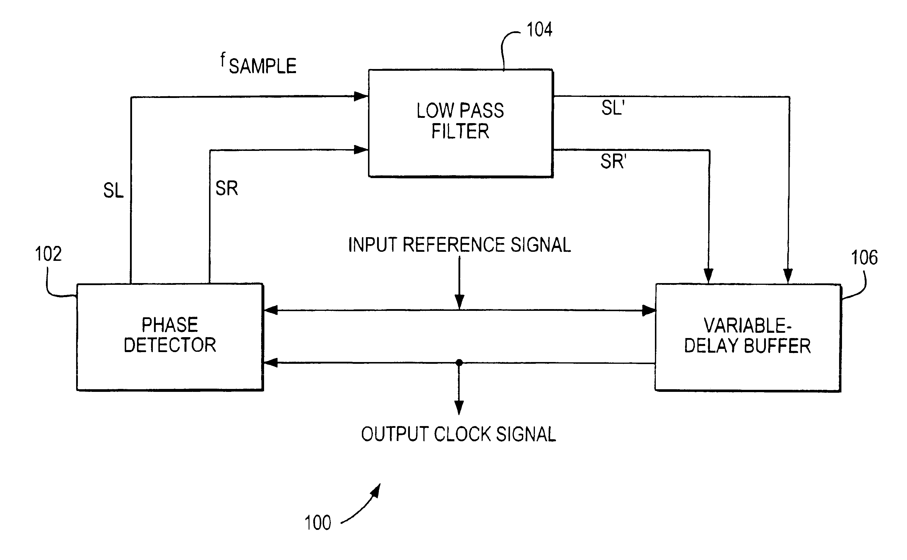
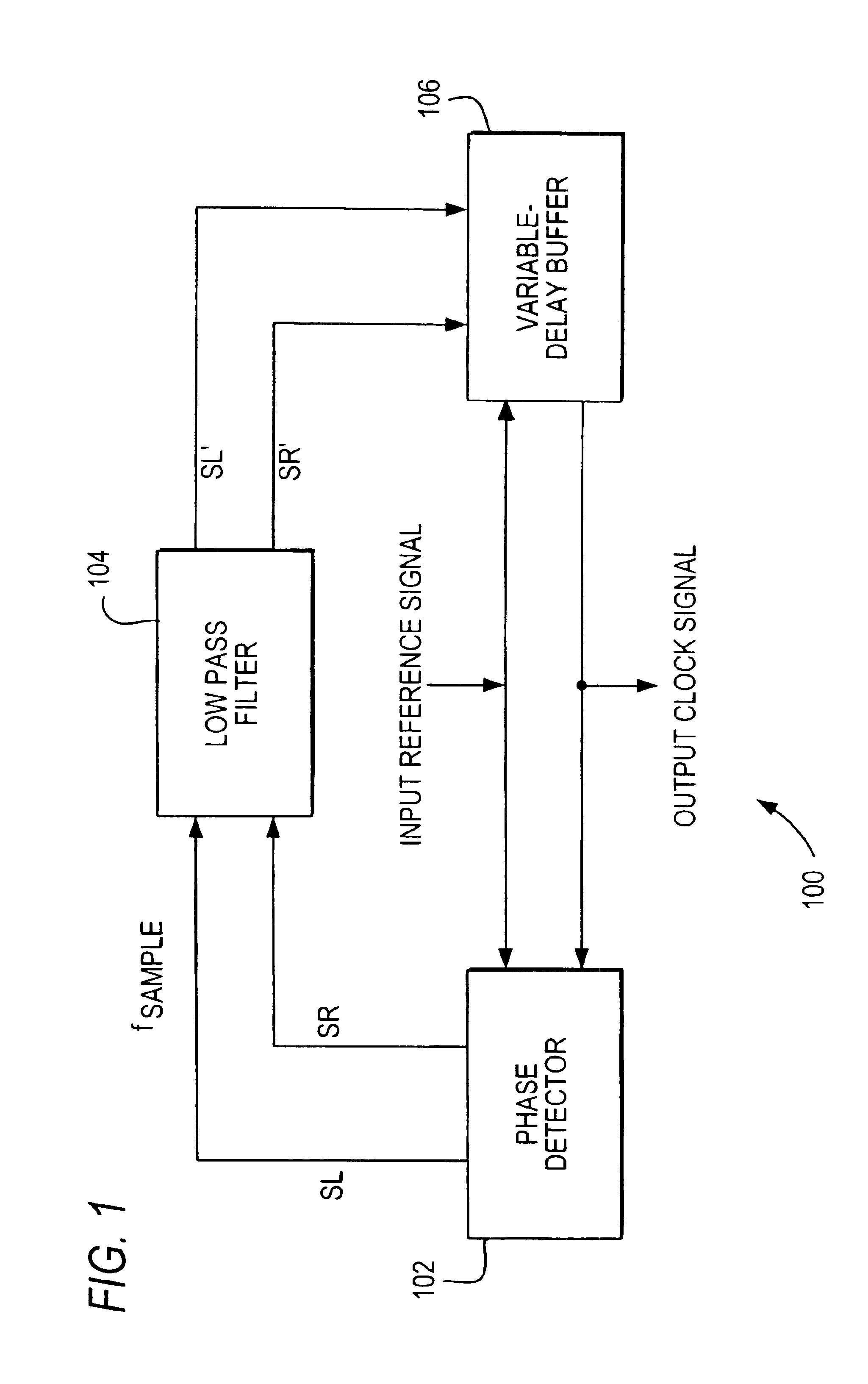
[0029]In phase detector 102 (not shown), a flip-flop generates SL and SR signals. The input signal clocks the flip-flop and the output clock signal is coupled to the data input of the flip-flop. An SL signal is generated in response to a logical zero flip-flop output, while an SR signal is generated in response to a logical one flip-flop output.

second embodiment

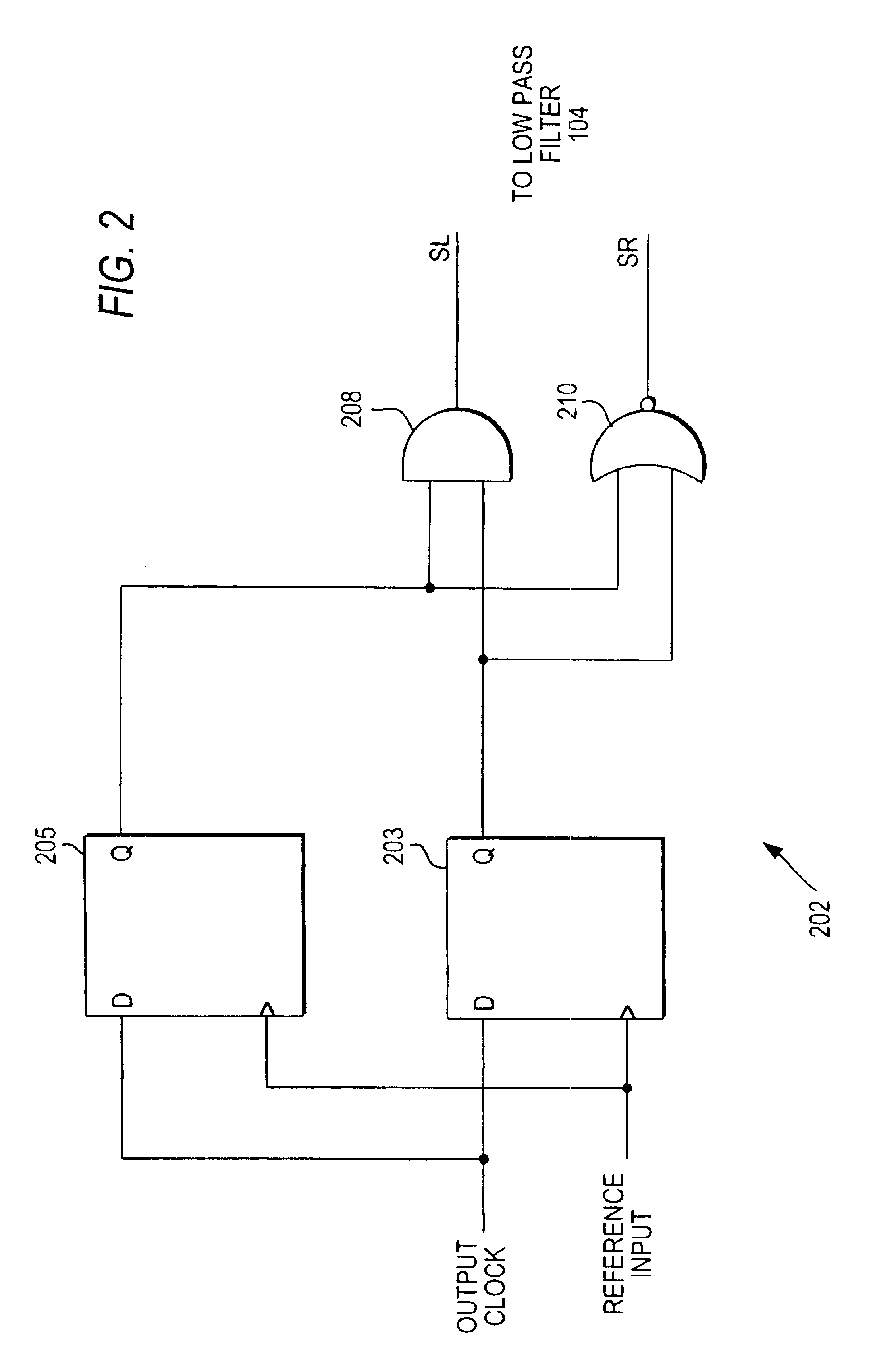
[0030]FIG. 2 shows phase detector 102, which is constructed with two flip-flops to preferably ensure greater stability. Phase detector 202 includes flip-flops 203 and 205 coupled to AND-gate 208 and NOR-gate 210 to generate SL and SR signals, respectively. When the output clock signal is a logical one at the rising edge of the input signal with respect to both flip-flops 203 and 205, the SR signal is asserted (e.g., logical one). When the output clock signal is a logical zero at the rising edge of the input signal with respect to both flip-flops 203 and 205, the SL signal is asserted (e.g., logical zero). Alternately, phase detector 202 can be constructed such that asserted SL and SR signals can be either a logical one or a logical zero.

[0031]Returning to FIG. 1, low pass filter 104 is coupled to phase detector 102 to receive SL and SR signals. Low pass filter 104, in accordance with the invention, provides filtered versions of SL and SR signals (i.e., SL′ and SR′ signals). Low pass...


PUM


Abstract

Circuits and methods are provided that reduce, if not prevent, the adverse effects of transient noise on phase adjustments made by digital delay lock loop (DLL) circuits, which typically generate a periodic output signal having a particular phase relationship with a periodic input signal. A digital low pass filter of a DLL circuit includes circuitry, such as, for example, a thermometer register, coupled to receive the outputs of a DLL phase detector. The low pass filter prevents the DLL circuit from making frequent changes to the phase of the DLL output signal.

Description

CROSS REFERENCE TO RELATED APPLICATION[0001]This is a continuation of commonly assigned U.S. patent application Ser. No. 09 / 997,721, filed Nov. 30, 2001, now U.S. Pat. No. 6,664,830.BACKGROUND OF THE INVENTION[0002]This invention relates to digital DLL (delay lock loop) circuits. More particularly, this invention relates to low pass filters in digital delay lock loop circuits.[0003]Digital delay lock loop circuits typically generate a clock signal based on a periodic reference signal (e.g., from an oscillator) that maintains a specific phase relationship with that reference signal. Digital delay lock loop circuits are often used, for example, in high-speed clocked memories such as SDRAMs (synchronous dynamic random access memories).[0004]A digital delay lock loop circuit usually includes a phase detector that detects a phase difference outside the specified phase relationship between the periodic reference signal and the periodic output signal, which is fed back to the phase detecto...

Claims


Application Information

Patent Timeline
Patent Type & Authority Patents(United States)
IPC IPC(8): H03L7/093H03L7/089H03L7/08H03L7/081
CPCH03L7/0814H03L7/089H03L7/093
Inventor MILLER, JAMES E.
Owner ROUND ROCK RES LLC
Why Eureka
Try Eureka