
Component operating with bulk acoustic waves, and having asymmetric/symmetrical circuitry

a technology of bulk acoustic waves and circuits, applied in piezoelectric/electrostrictive/magnetostrictive devices, piezoelectric/electrostriction/magnetostriction machines, electrical apparatus, etc., can solve problems such as varying amplitudes of signals, and achieve the effect of reducing discrepancies in phase differen

Active Publication Date: 2005-07-12
SNAPTRACK
View PDF5 Cites 101 Cited by
  • Summary
  • Abstract
  • Description
  • Claims
  • Application Information

AI Technical Summary

Benefits of technology

The present invention provides a component operating with bulk acoustic waves that has an asymmetric and a symmetrical port, with the phase difference between the symmetrical signals being approximately 180°. The component has a first resonator and a second resonator that are stacked one on top of each other and are acoustically coupled to one another by way of a coupling layer system. The coupling layer system has an alternating sequence of at least two λ / 4 mirror layers with different acoustic impedance and a compensation layer that has a thickness of approximately λ / 8. The component can have further resonators that are stacked one on top of each other and are acoustically coupled to one another by way of further coupling layer systems. The acoustic mirror can have layers with different acoustic impedance and the compensation layer can be combined with the mirror layers or with the layers of the acoustic mirror. The component can achieve a reduced discrepancy in the phase difference of 180° between the signals at the symmetrical port and keep the amplitude of these signals approximately the same.

Problems solved by technology

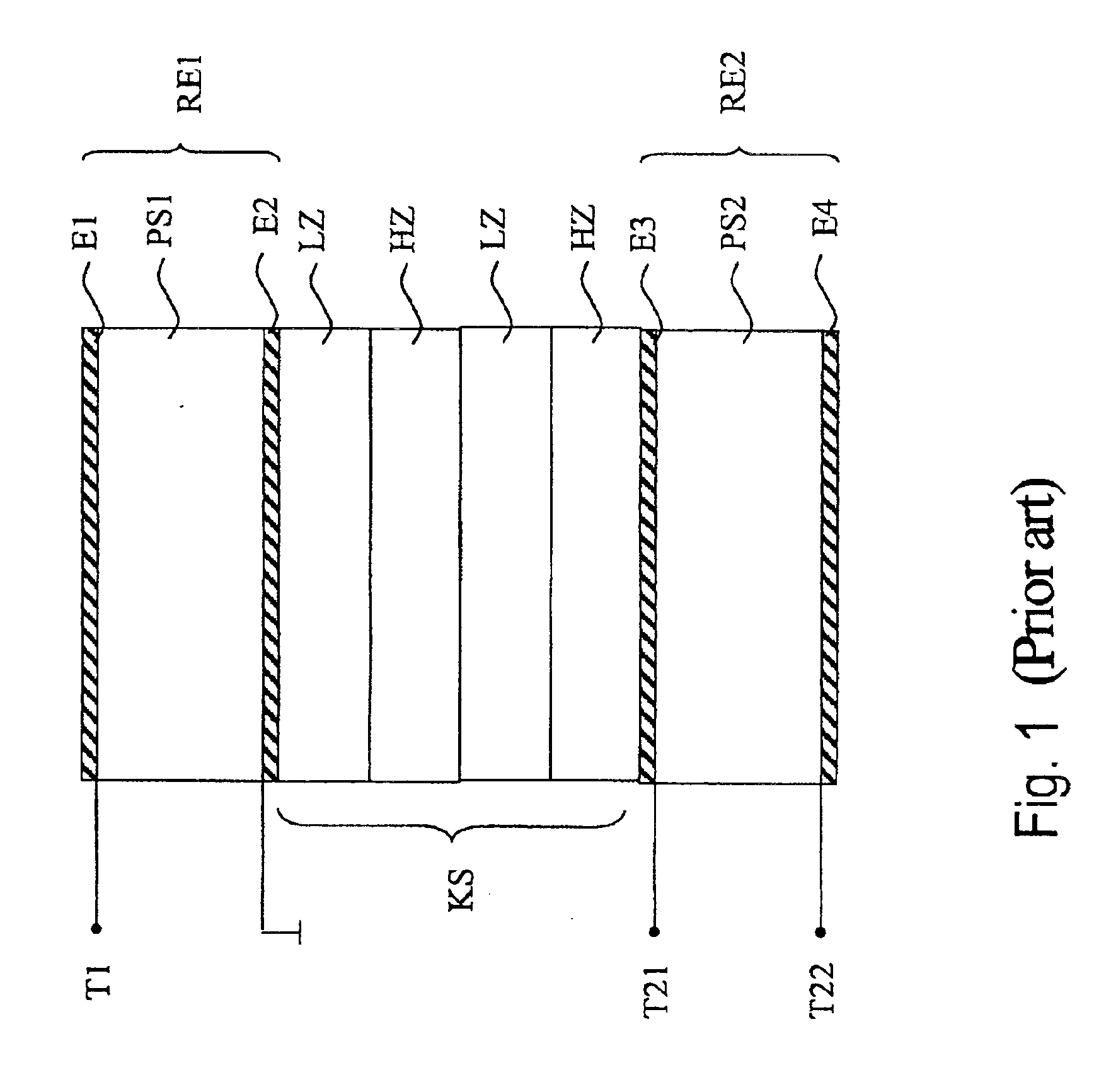
This stacked crystal filter has the disadvantage that the components of the acoustic wave which are reflected on different boundary surfaces of the mirror layers of the coupling layer system have a phase difference between them and thus, in particular, contribute to the discrepancy in the phase difference of the symmetrical signals at the second port of about 15 to 20° from the desired phase difference value of 180°.
Furthermore, this leads to varying amplitudes of the signals at the symmetrical port, which has been found to be disadvantageous for the functionality of the stages of an electronic circuit (for example, of an amplifier) to be connected downstream.

Method used


Image

  • Component operating with bulk acoustic waves, and having asymmetric/symmetrical circuitry
  • Component operating with bulk acoustic waves, and having asymmetric/symmetrical circuitry
  • Component operating with bulk acoustic waves, and having asymmetric/symmetrical circuitry

Examples


Embodiment Construction

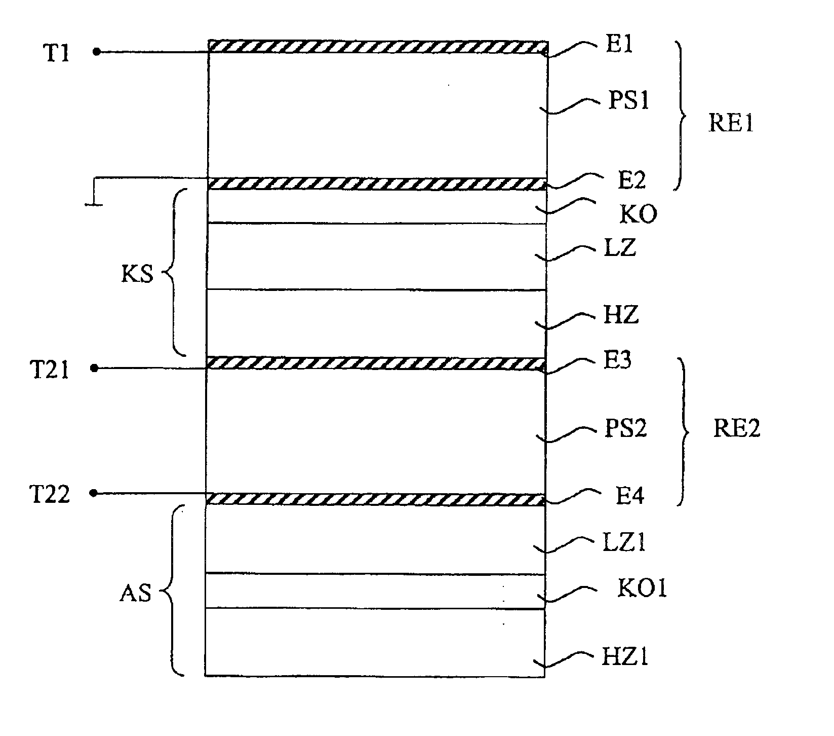
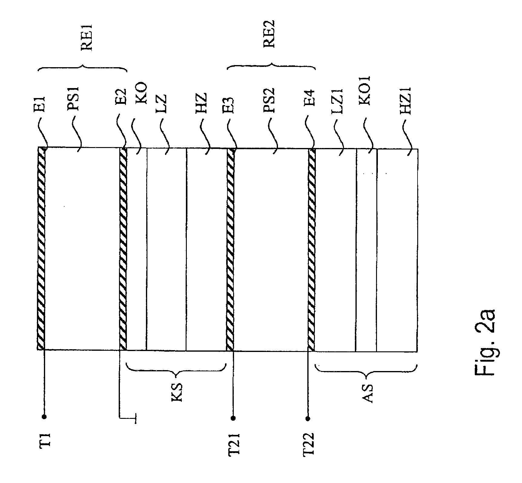
[0035]FIG. 2a shows an embodiment of a component according to the invention, illustrated schematically. A first resonator RE1 is formed by a first piezoelectric layer PS1, a first electrode E1 and a second electrode E2, and is connected between a signal-carrying connection T1 of a first asymmetric electrical port, and ground. A second resonator RE2 is formed by a second piezoelectric layer PS2, a third electrode E3 and a fourth electrode E4, and is connected between a first connection T21 and a second connection T22 of a second, symmetrical electrical port. The resonators RE1 and RE2 are acoustically connected to one another by way of a coupling layer system KS. The coupling layer system KS has alternately arranged, partially permeable mirror layers with a high and a low acoustic impedance (reference symbols HZ and LZ, respectively), which preferably have a thickness of approximately λ / 4. The coupling layer system KS furthermore has a compensation layer KO which, in this exemplary e...


PUM


Abstract

A component operating with bulk acoustic waves has two Bulk Acoustic Wave (BAW) resonators that are stacked and are acoustically coupled to one another, with a first resonator being connected to an asymmetric port, and a second resonator being connected to a symmetrical port. The acoustic coupling is provided by a partially permeable coupling layer system, which has an alternating sequence of at least two λ / 4 mirror layers with different acoustic impedance. The coupling layer system furthermore has a compensation layer, which has an approximate thickness of λ / 8. The compensation layer according to the invention makes it possible to match any discrepancy in the phase difference (which is caused by reflections on the mirror layers) from the predetermined 180° between the connections of the symmetrical port to approximately 180°.

Description

BACKGROUND OF THE INVENTION[0001]The invention relates to a component operating with bulk acoustic waves, and particularly to a stacked crystal filter with thin-film resonators that are stacked one on top of the other and are connected to one another (or Thin Film Bulk Acoustic Wave Resonator, “FBAR”), which is also referred to as a Bulk Acoustic Wave resonator (or BAW resonator).[0002]Resonators such as these are particularly suitable for bandpass radio-frequency filters in modern filter technology and may, for example, be used in mobile communication appliances.[0003]A resonator operating with bulk acoustic waves has at least one piezoelectric layer that is arranged between two metal layers (electrodes). In a stacked crystal filter, two or more resonators are stacked one on top of the other, for example by a second piezoelectric layer being deposited first of all on the uppermost electrode of the lower resonator, after which an upper electrode is deposited for the upper resonator....

Claims


Application Information

Patent Timeline
Patent Type & Authority Patents(United States)
IPC IPC(8): H03H9/00H03H9/58
CPCH03H9/0095H03H9/584H03H9/589
Inventor UNTERBERGER, MICHAEL
Owner SNAPTRACK
Learn More