Interferometers for measuring changes in optical beam direction

a technology of interferometer and optical beam, which is applied in the direction of optical radiation measurement, instruments, measurement devices, etc., can solve the problem of not being able to achieve the desired precision required for important industrial applications

Inactive Publication Date: 2005-07-12
ZYGO CORPORATION
View PDF15 Cites 24 Cited by
  • Summary
  • Abstract
  • Description
  • Claims
  • Application Information

AI Technical Summary

Problems solved by technology

If such effects are not compensated, it is often not possible to achieve the desired precision required of important industrial applications such as those practiced in the fabrication of semiconductor devices.

Method used


Image

  • Interferometers for measuring changes in optical beam direction
  • Interferometers for measuring changes in optical beam direction
  • Interferometers for measuring changes in optical beam direction

Examples


first embodiment

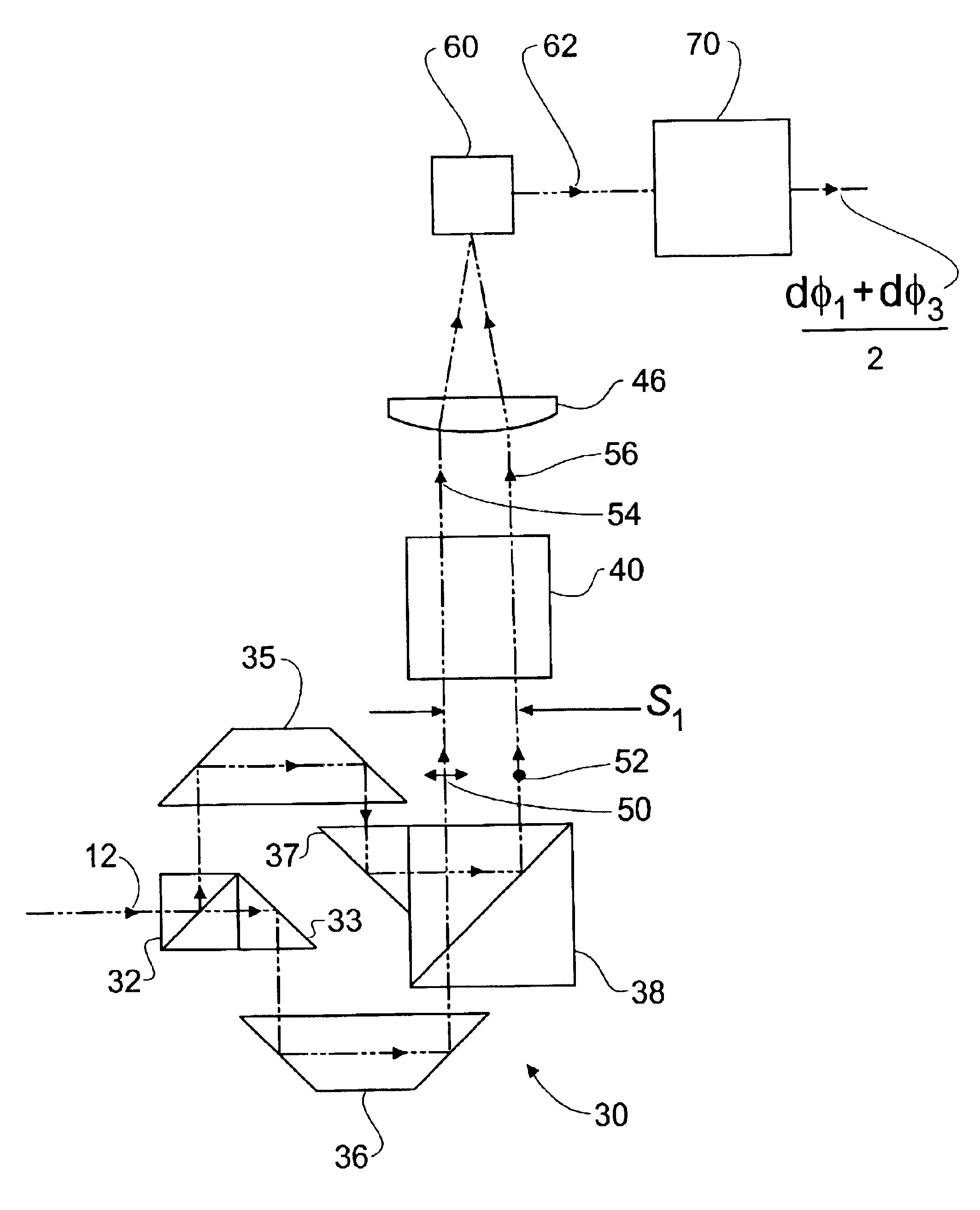
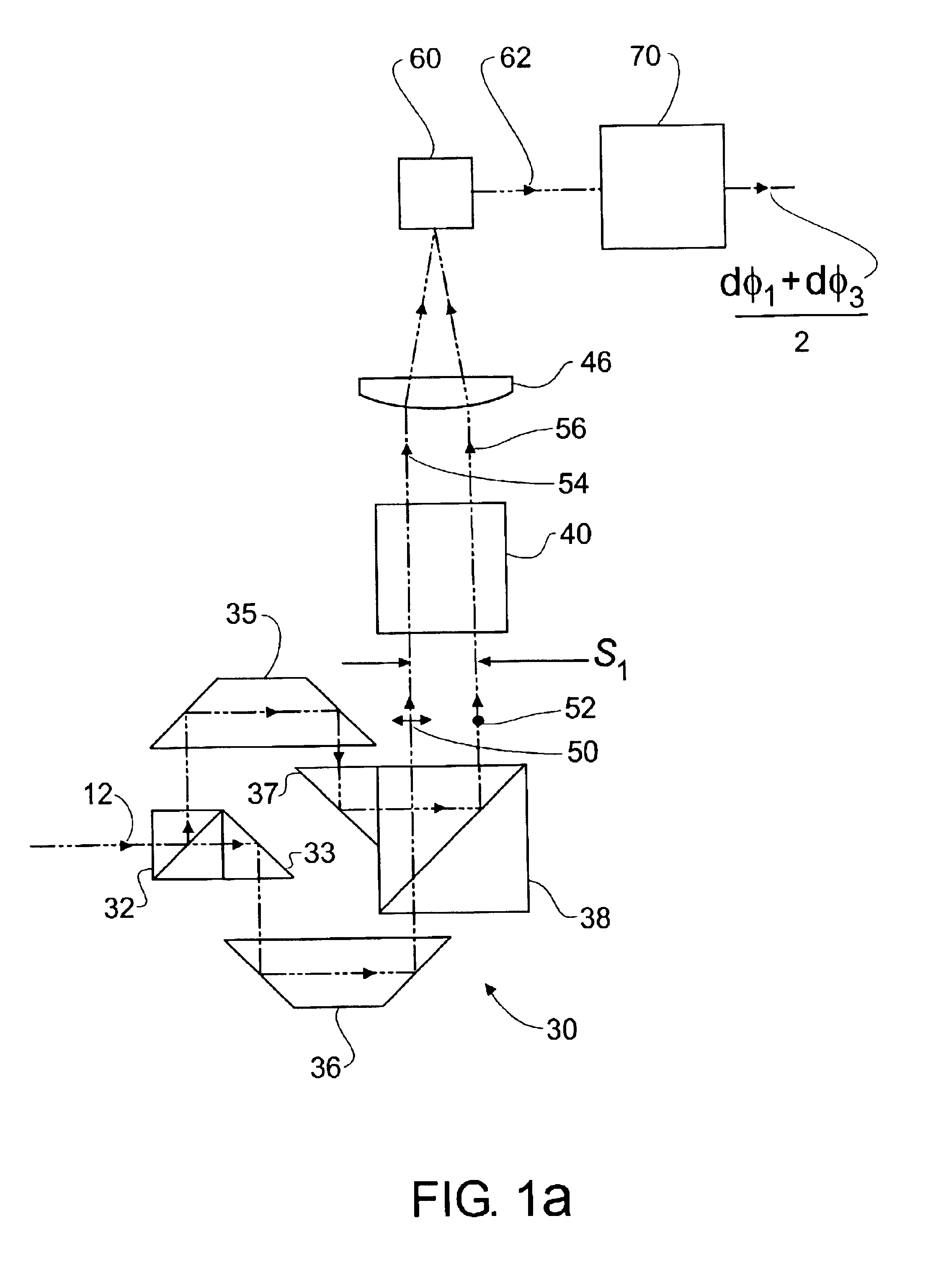
[0037]Note that the optical path in glass for each of beams 54 and 56 through beam-shearing assembly 30 and analyzer 40 are preferably the same. This feature of the apparatus design of the first embodiment produces a high stability interferometer system with respect to changes in temperature.

[0038]Heterodyne signal s1 may be written as

s1=A1 cos(ω1t+φ1+ζ1)  (1)

where

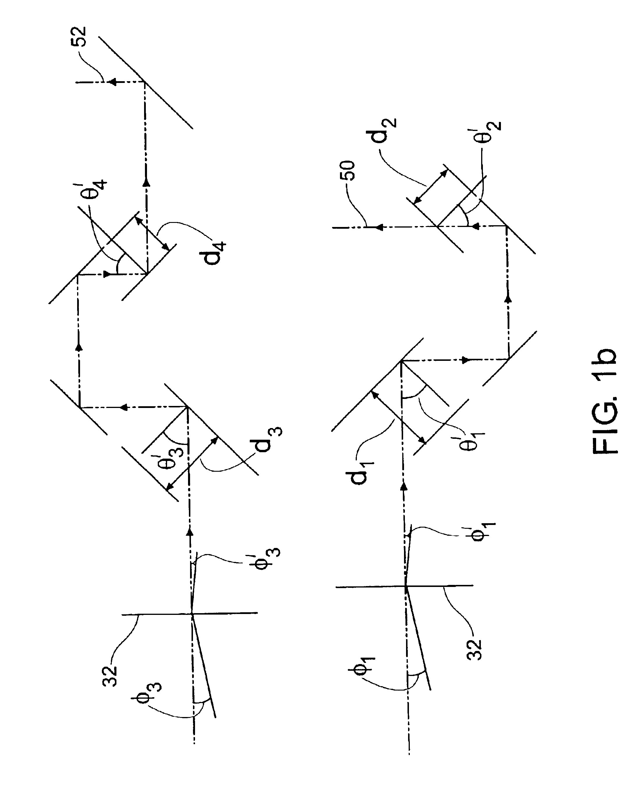
φ1=2k1n[d1 cosθ1′+d2 cosθ2′−d3 cosθ3′−d4 cosθ4′],  (2)

ω1=2πf1, ζ1 is an offset phase not associated with phase φ1, k1=2π / λ1, λ1 is the wave length of input beam 12, θ1′ and θ2′ are angles of incidence of beam 50 at right angle prism 33 and at the polarizing beamsplitter 38, respectively, (see FIG. 1b), θ3′ and θ4′ are angles of incidence of beam 52 at polarizing beamsplitter 32 and at right angle prism 37, respectively, (see FIG. 1b), and d1, d2, d3, and d4 are defined in FIG. 1b. It has been assumed in Eq. (2) for purposes of demonstrating the features of the present invention in a simple fashion, without departing from t...

second embodiment

[0081]An advantage of the stacked configuration of the variant of the second embodiment is a compact interferometer system with reduced effects of temperature changes. Another advantage of the stacked configuration is that one common beam-shearing assembly can be used for both angle measuring interferometers. The height of elements of beam-shearing assembly 30 are increased so that beam-shearing assembly 30 serves the function of both beam-shearing assemblies 30 and 130.

[0082]The remaining description of the variant of the second embodiment is the same as corresponding portions of the description given for the second embodiment.

[0083]Other variants of the second embodiment are described wherein the second embodiment is configured for an input beam having a single frequency component. The descriptions of the other variants of the second embodiment are the same as corresponding portions of the descriptions given for the first and second variants of the first embodiment and correspondi...

third embodiment

[0086]The angle measured by the third embodiment is the difference in changes in directions of propagation [dφ1−dφ3] / 2 of the two components of input beam 12 as a result of the image inversion of beam 252 introduced by the addition of Penta prism 135.

[0087]The remaining description of the third embodiment is the same as corresponding portions of the description given for the first embodiment.

[0088]There are first and second variants of the third embodiment that correspond to the first and second variants of the first embodiment of the present invention.

[0089]A fourth embodiment of the present invention is described wherein differential angle measurements of the directions of propagation two beam components are made in two orthogonal planes. The fourth embodiment comprises non-polarizing beamsplitter 20 (FIG. 2a) and two angle measuring interferometers. The two differential angle-measuring interferometers measure the changes in the difference in directions of propagation of two compo...


PUM


Abstract

Apparatus for measuring angular changes in the direction of travel of a light beam comprising at least one beam shearing assembly for separating, preferably orthogonally polarized, components of the light beam and introducing a lateral shear between them. An analyzer operates on the components to provide them with a common polarization state. A lens focuses the commonly polarized components of the light beam to a spot in a detector plane, and a detector operates to generate an electrical signal having a phase that varies in accordance with the angular change of the light beam in at least one plane. Electronic means receive the electrical signal, determines the phase therefrom, and converts the phase to the angular change in the direction of travel of the light beam.

Description

CROSS REFERENCE TO RELATED APPLICATIONS[0001]This application claims priority from U.S. Provisional Patent application Ser. No. 60 / 344,879 filed on Oct. 19, 2001 in the name of Henry Allen Hill with the title “Interferometers For Measuring Changes In Optical Beam Direction” and U.S. Provisional Patent application Ser. No. 60 / 351,496 filed on Jan. 24, 2002 in the name of Henry Allen Hill, et al. with the title “Interferometers For Measuring changes In Optical Beam Direction”, the contents of both provisionals being incorporated herein by reference.BACKGROUND OF THE INVENTION[0002]This invention generally relates to interferometry and more particularly to interferometric apparatus and methods by which highly precise metrology is practiced.[0003]In highly precise metrology, it is required to understand and compensate for changes in the direction of propagation of various individual optical beams in which information is encoded about distances and / or angles under measurement. Changes in...

Claims


Application Information

Patent Timeline
Patent Type & Authority Patents(United States)
IPC IPC(8): G01B9/02G01J9/00
CPCG01J9/00G01B9/02003G01B9/02021G01B9/02027G01B9/02098G01B2290/70G01B2290/45
Inventor HILL, HENRY ALLENKREUZER, JUSTIN L.
Owner ZYGO CORPORATION
Why Eureka
Try Eureka