Control device for brushless direct current motor sensorless based on 12-beat control and method thereof

A brush DC motor and control device technology, which is applied in the direction of output power conversion device, control system, electronic commutator, etc., can solve the problem of high-performance occasions where the 120° conduction-type square wave driving method cannot be applied, increase system volume and Cost, complex control algorithm and other issues, to achieve the effect of large output, low cost, small torque ripple

Inactive Publication Date: 2009-10-14
SHANGHAI UNIV
View PDF0 Cites 30 Cited by
  • Summary
  • Abstract
  • Description
  • Claims
  • Application Information

AI Technical Summary

Problems solved by technology

But the traditional sine wave current driving method, such as three-phase current tracking method, i d , i q Type vector control method, etc. In addition to the complex control algorithm, expensive position sensors such as photoelectric encoders are also required to obtain continuous rotor position signals, which increases the size and cost of the system. For consumer products such as home appliances, the cost is one very important constraints
Therefore, the defect of the traditional brushless DC motor control method is that the convenient and low-cost 120° conduction square wave driving met

Method used


Image

  • Control device for brushless direct current motor sensorless based on 12-beat control and method thereof
  • Control device for brushless direct current motor sensorless based on 12-beat control and method thereof
  • Control device for brushless direct current motor sensorless based on 12-beat control and method thereof

Examples


Embodiment Construction

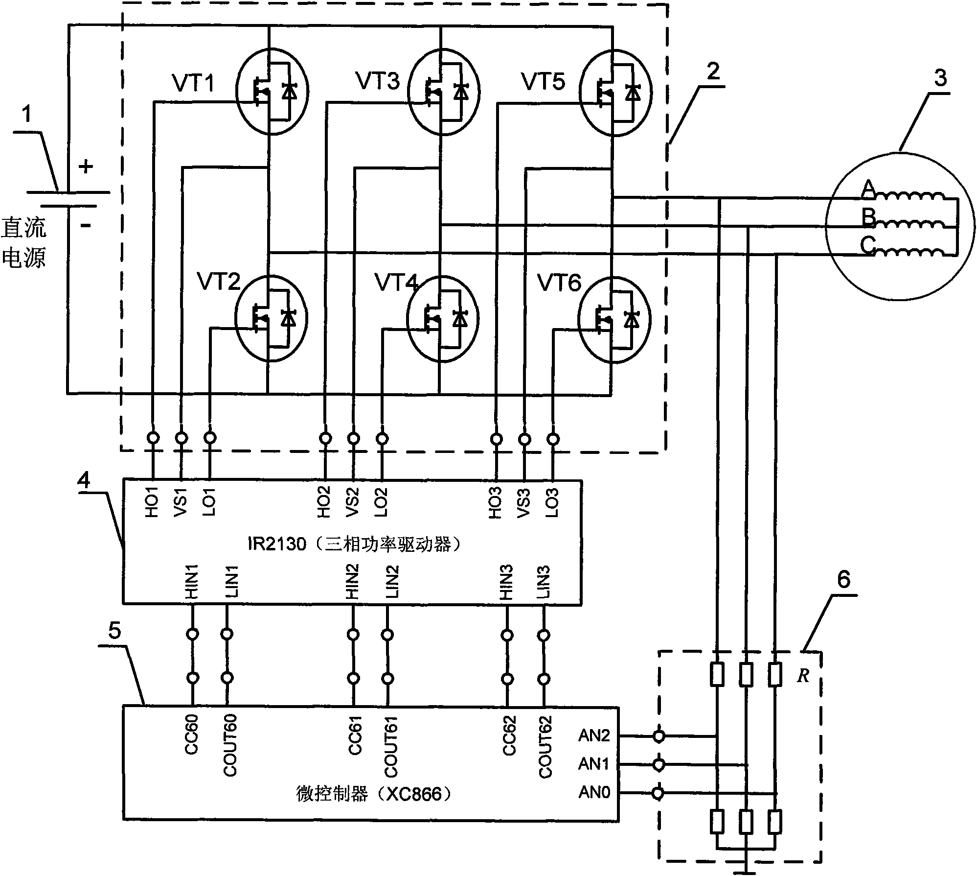
[0012] Preferred embodiments of the present invention are described as follows in conjunction with the accompanying drawings: see image 3 , the brushless DC motor position sensorless control device based on 12-beat control includes a DC power supply 1, a three-phase inverter 2, a brushless DC motor 3, a three-phase inverter power device drive circuit 4, a microcontroller 5 and Rotor position detection circuit 6. The DC power supply 1 is connected to the brushless DC motor 3 through the three-phase inverter 2; the rotor position detection circuit 6 is connected to the brushless DC motor 3 for detection and the output signal is directly connected to the analog-to-digital conversion input pin of the microcontroller 5; The six outputs of the microcontroller 5 are connected to the three-phase inverter 2 through the three-phase inverter power device driving circuit 4 . The driving circuit 4 of the power device of the three-phase inverter adopts an IR2130 type chip, and the microco...


PUM


Abstract

The invention relates to a control device for a brushless direct current motor sensorless based on 12-beat control and a method thereof. The device comprises a direct current power supply, a three-phase inverter, a brushless direct current motor, a drive circuit of a power device of the three-phase inverter, a microcontroller and a rotor position detection circuit, wherein the direct current power supply is connected with the brushless direct current motor through the three-phase inverter; after the rotor position detection circuit is connected with the brushless direct current motor for detecting, an output signal is directly connected with an analog-to-digital conversion input pin of the microcontroller; and six-path output of the microcontroller is connected to the three-phase inverter through the drive circuit of the power device of the three-phase inverter. The method detects terminal voltage of an inactive phase winding in a two-pipe conducting region at PWM conducted moment by an analog-to-digital conversion unit embedded in an XC866 singlechip, and acquires back electromotive force zero crossing as accordance of 12-beat phase conversion, thereby reducing the requirement of the adopted control device of the brushless direct current motor sensorless on a peripheral circuit, and achieving the aims of not only effectively inhibiting electromagnetic torque pulsation, but also reducing the system cost.

Description

Technical field: [0001] The invention relates to a position sensorless control device and method for a brushless direct current motor, in particular to a position sensorless control device and method for a brushless direct current motor based on 12-beat control with low cost and capable of effectively suppressing electromagnetic torque ripple. Background technique: [0002] At present, the conventional method used to control the brushless DC motor is the 120° conduction type three-phase six-state square wave drive method. This method usually uses 3 Hall elements as position sensors, and performs 6 commutation steps within 360° electrical angle. The algorithm is simple, and the drive control circuit is also relatively simple, so the cost is low and it is suitable for many large-scale applications. However, the outstanding disadvantage of this method is that the winding current contains rich harmonics, which makes the electromagnetic torque ripple large, resulting in poor runn...

Claims


Application Information

Patent Timeline
IPC IPC(8): H02P6/08H02P6/18H02M7/5395H02P6/10H02P6/182
Inventor 崔巍马艳丽范洪伟孙杰
Owner SHANGHAI UNIV
Why Eureka
Try Eureka