Apparatus for controlling internal combustion engine

a technology for controlling an internal combustion engine and an apparatus, which is applied in the direction of machines/engines, process and machine control, output power, etc., can solve the problems of inability to control the internal egr amount with a high accuracy, and the apparatus cannot optimize the ignition timing

Active Publication Date: 2005-07-12
TOYOTA JIDOSHA KK
View PDF10 Cites 29 Cited by
  • Summary
  • Abstract
  • Description
  • Claims
  • Application Information

AI Technical Summary

Benefits of technology

[0006]Accordingly, it is an objective of the present invention to provide an apparatus for controlling an internal combustion engine, which apparatus easily an properly controls the engine based on the relationship between the state of a variable valve actuation mechanism and the amount of internal EGR.

Problems solved by technology

However, the apparatus of the above publication does not clearly define the relationship between the state of the variable valve actuation mechanism and changes in the amount of internal EGR amount.
Thus, the apparatus can hardly optimize the ignition timing in relation to changes in the internal EGR amount.
However, since the relationship between the state of the variable valve actuation mechanism and changes in the amount of internal EGR amount is not clearly defined, the internal EGR amount cannot be controlled with a high accuracy.

Method used


Image

  • Apparatus for controlling internal combustion engine
  • Apparatus for controlling internal combustion engine
  • Apparatus for controlling internal combustion engine

Examples


first embodiment

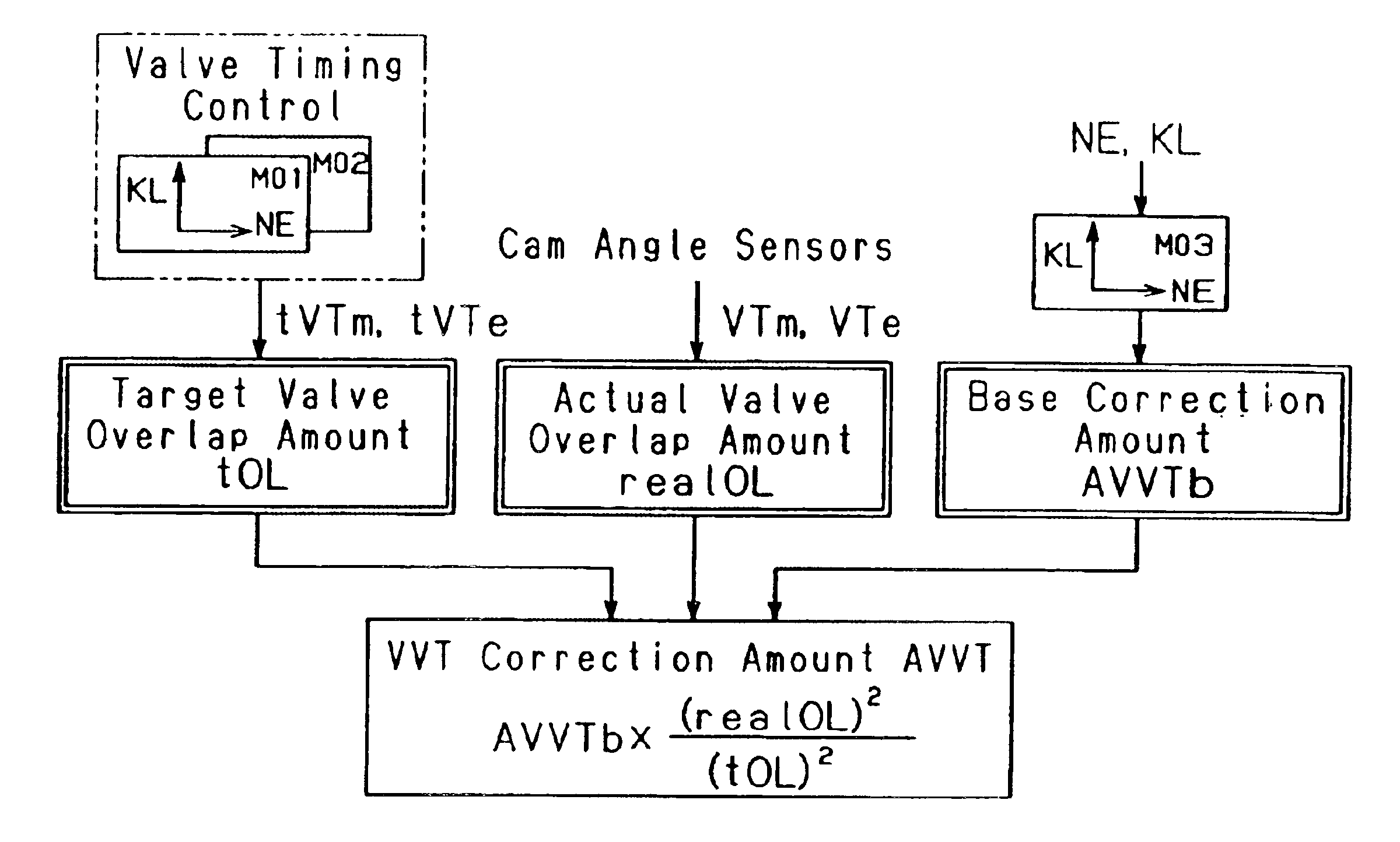
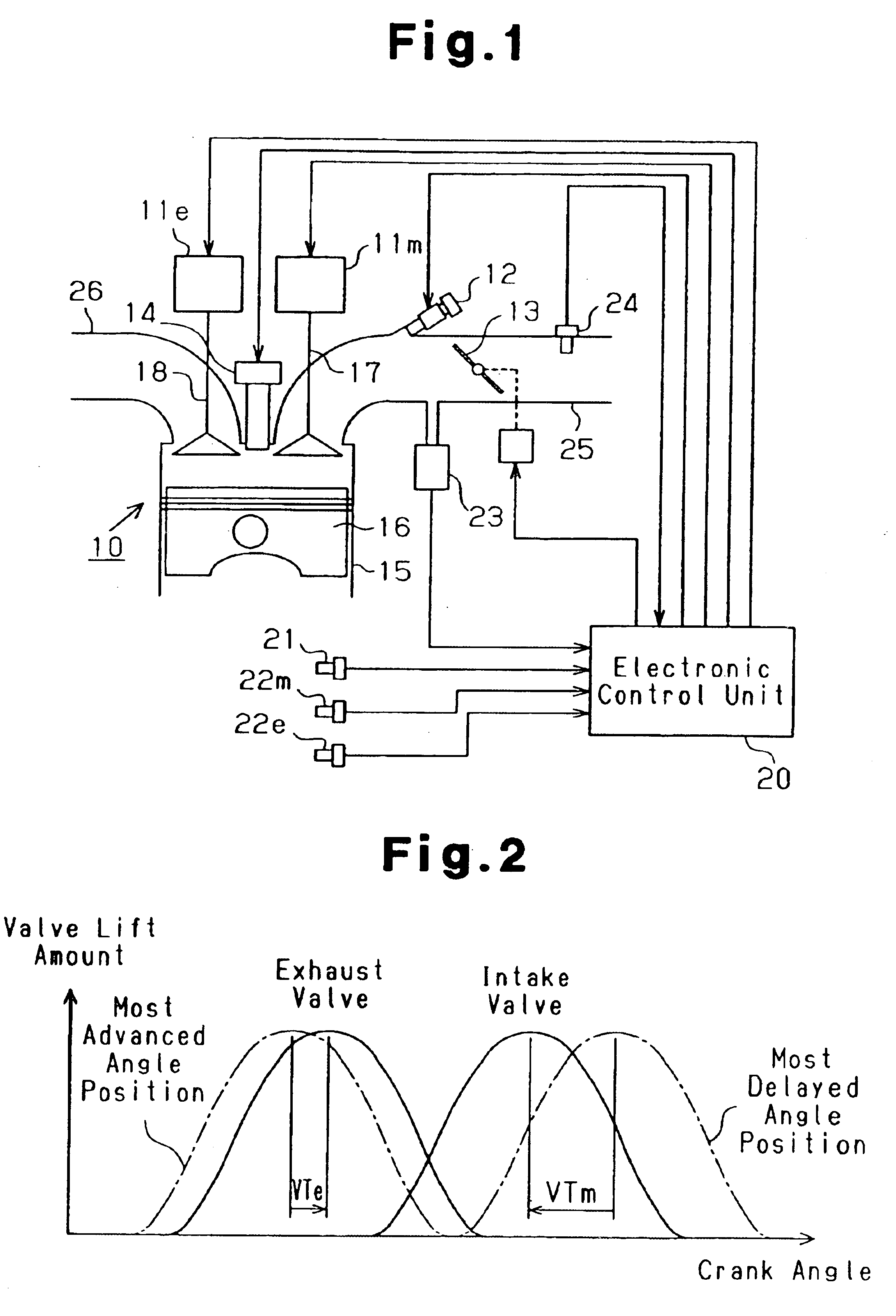
[0028]An apparatus for controlling an internal combustion engine according to the present invention will now be described with reference to the drawings.

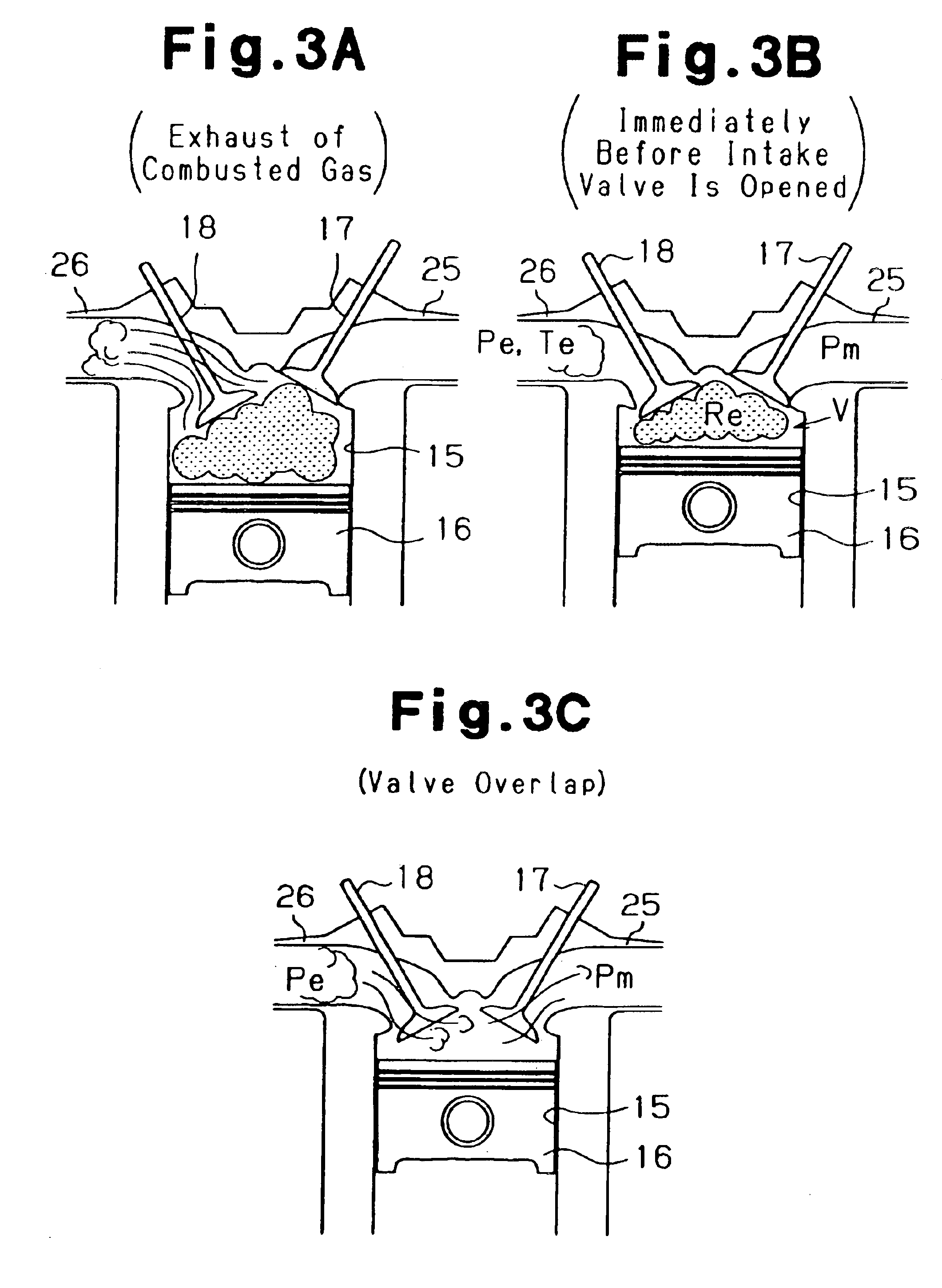
[0029]As shown in FIG. 1, an internal combustion engine 10 of this embodiment includes one or more cylinders 15, each of which accommodates a piston 16, at least one intake valve 17, and at least one exhaust valve 18. Each intake valve 17 and each exhaust valve 18 correspond to one of the cylinders 15. An intake pipe 25, which is an intake passage, is coupled to the cylinder 15. The intake valve 17 selectively connects and disconnects the intake pipe 25 with the cylinder 15. An exhaust pipe 26, which is an exhaust passage, is coupled to the cylinder 15. The exhaust valve 18 selectively connects and disconnects the exhaust pipe 26 with the cylinder 15.

[0030]The engine 10 has various sensors that detect the running state of the engine 10. For example, a crank angle sensor 21 is provided in the vicinity of a crankshaft, which is an out...


PUM


Abstract

An electronic control unit corrects ignition timing according to changes in an internal EGR amount accompanying actuation of a variable valve actuation mechanism used in an internal combustion engine. The electronic control unit computes a base correction amount AVVTb based on an engine speed NE and an engine load ratio KL. The control unit multiplies the base correction amount AVVTb by the ratio of a square number of an actual valve overlap amount realOL to a square number of a target valve overlap amount tOL, thereby computing a VVT correction amount AVVT of ignition timing. As result, the engine is easily and properly controlled based on the relationship between the state of the variable valve actuation mechanism and changes in the internal EGR amount.

Description

BACKGROUND OF THE INVENTION[0001]The present invention relates to an apparatus for controlling an internal combustion engine that has a variable valve actuation mechanism for varying the valve overlap state of intake and exhaust valves.[0002]Internal combustion engines having a variable valve actuation mechanism have been proposed to improve the intake efficiency, decrease NOx, or exhaust emission, and improve the fuel consumption by reducing pumping loss caused by internal EGR. A variable valve actuation mechanism varies the actuation of intake and exhaust valves according to the running state of an engine. For example, variable valve timing mechanisms and variable valve lift mechanisms are widely used for on-vehicle internal combustion engines. A variable valve timing mechanism varies timings of intake and exhaust valves, or valve timing. A variable valve lift mechanism varies the valve lift of intake and exhaust valves.[0003]In an engine having such a variable valve actuation mec...

Claims


Application Information

Patent Timeline
Patent Type & Authority Patents(United States)
IPC IPC(8): F02D13/02F02P5/15F02M25/07
CPCF02D13/0219F02D13/0261F02D41/0062F02M25/0752F02P5/1516F02D13/0207F02D2041/001Y02T10/46Y02T10/18Y02T10/47F02M26/01Y02T10/12Y02T10/40
Inventor UCHIDA, TAKEFUMIMUTO, HARUFUMI
Owner TOYOTA JIDOSHA KK
Why Eureka
Try Eureka