Dissection of printed edges from a fabrication layout for correcting proximity effects

a technology of proximity effect and fabrication layout, which is applied in the direction of photomechanical treatment originals, instruments, photomechanical equipment, etc., can solve the problems of large correction and prevent the convergence of layout overall corrections, and achieve the effect of speeding up the analysis process

Inactive Publication Date: 2005-07-12
SYNOPSYS INC
View PDF87 Cites 215 Cited by
  • Summary
  • Abstract
  • Description
  • Claims
  • Application Information

AI Technical Summary

Benefits of technology

[0030]According to techniques of the present invention, edges of polygons in a mask layout are dissected into segments defined by dissection points, with each segment having an evaluation point, according to modified dissection rules. These techniques allow the spacing of evaluation points and dissection points to be automatically adapted to portions of each edge where cha

Problems solved by technology

A segment that is too short, for example in a corner, may result in a very large c

Method used


Image

  • Dissection of printed edges from a fabrication layout for correcting proximity effects
  • Dissection of printed edges from a fabrication layout for correcting proximity effects
  • Dissection of printed edges from a fabrication layout for correcting proximity effects

Examples


Embodiment Construction

[0063]Techniques are described for correcting fabrication layouts for proximity effects during the fabrication of printed features layers, such as in integrated circuits.

[0064]Functional Overview

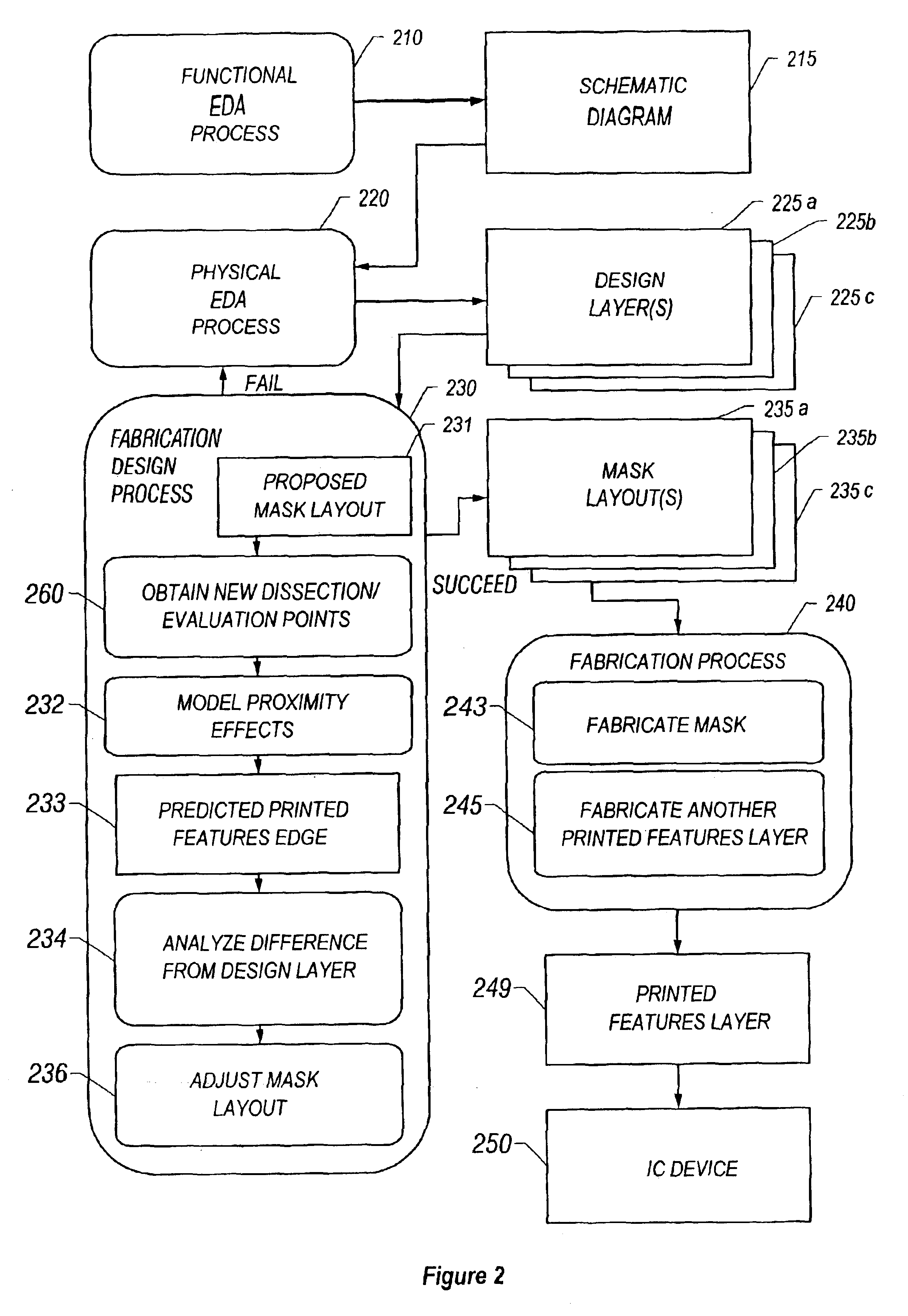
[0065]FIG. 2 shows the processes and layouts produced according to the present techniques for designing and fabricating printed features layers 249 for devices 250. The conventional processes are modified to include new techniques for selecting evaluation and dissection points, as represented in FIG. 2 by process 260.

[0066]The conventional processes include the Functional EDA process 210 that produces the schematic diagram 215. The physical EDA process 220 converts the schematic diagram to a design layout made up of one or more design layers 225 (e.g. design layers 225a, 225b, and 225c). After mask layouts 235 (e.g. mask layouts 235a, 235b, and 235c) are produced, the conventional processes employ a fabrication process 240 to produce the printed features layer 249. The printed features layer...


PUM

PropertyMeasurementUnit
Lengthaaaaaaaaaa
Distanceaaaaaaaaaa
Proximity effectaaaaaaaaaa

Abstract

Techniques for fabricating a device include forming a fabrication layout, such as a mask layout, for a physical design layer, such as a design for an integrated circuit, and identifying evaluation points on an edge of a polygon corresponding to the design layer for correcting proximity effects. Techniques include correcting for proximity effects associated with an edge in a first fabrication layout by determining whether any portion of the edge corresponds to a target edge in a design layer. The first fabrication layout corresponds to the design layer that indicates target edges for a printed features layer. If any portion of the edge corresponds to the target edge, then it is determined whether to establish an evaluation point on the edge. Then it is determined how to correct the edge for proximity effects based on the evaluation point. In case it is determined that no portion of the edge corresponds to the target edge, then no evaluation point is selected on the edge.

Description

RELATED APPLICATIONS[0001]The present application is a divisional of commonly owned U.S. patent application Ser. No. 09 / 676,375, “DISSECTION OF PRINTED EDGES FROM A FABRICATION LAYOUT FOR CORRECTING PROXIMITY EFFECTS” filed Sep. 29, 2000 now U.S. Pat. No. 6,625,801 by Christophe Pierrat and Youping Zhang.[0002]This application is related to U.S. patent application Ser. No. 09 / 675,582, entitled “Dissection Of Corners In A Fabrication Layout For Correcting Proximity Effects,” filed on Sep. 29, 2000, invented by Christophe Pierrat and Youping Zhang.[0003]This application is related to U.S. patent application Ser. No. 09 / 675,197, entitled “Dissection Of Edges With Projection Points In A Fabrication Layout For Correcting Proximity Effects,” filed on Sep. 29, 2000, invented by Christophe Pierrat and Youping Zhang.[0004]This application is related to U.S. patent application Ser. No. 09 / 676,356, entitled “Selection Of Evaluation Point Locations Based on Proximity Effects Model Amplitudes Fo...

Claims


Application Information

Patent Timeline
IPC IPC(8): G03F1/14B32B3/10G03F7/20G06F17/50G03F1/00G03F1/36
CPCG03F1/144G03F1/36Y10T428/24802
Inventor PIERRAT, CHRISTOPHEZHANG, YOUPING
Owner SYNOPSYS INC
Why Eureka
Try Eureka