Duplexer with an impedance matching circuit and an electronic device using the same

Inactive Publication Date: 2005-07-19
TAIYO YUDEN KK
View PDF15 Cites 14 Cited by
  • Summary
  • Abstract
  • Description
  • Claims
  • Application Information

AI Technical Summary

Benefits of technology

[0011]It is an object of the present invention to provide a compact duplexer havi

Problems solved by technology

However, the above-mentioned structure has a disadvantage resulting from the structure in which the upper and lower ground patterns are close to the impedance matching circuit line.
The close location causes

Method used


Image

  • Duplexer with an impedance matching circuit and an electronic device using the same
  • Duplexer with an impedance matching circuit and an electronic device using the same
  • Duplexer with an impedance matching circuit and an electronic device using the same

Examples


Example

First Embodiment

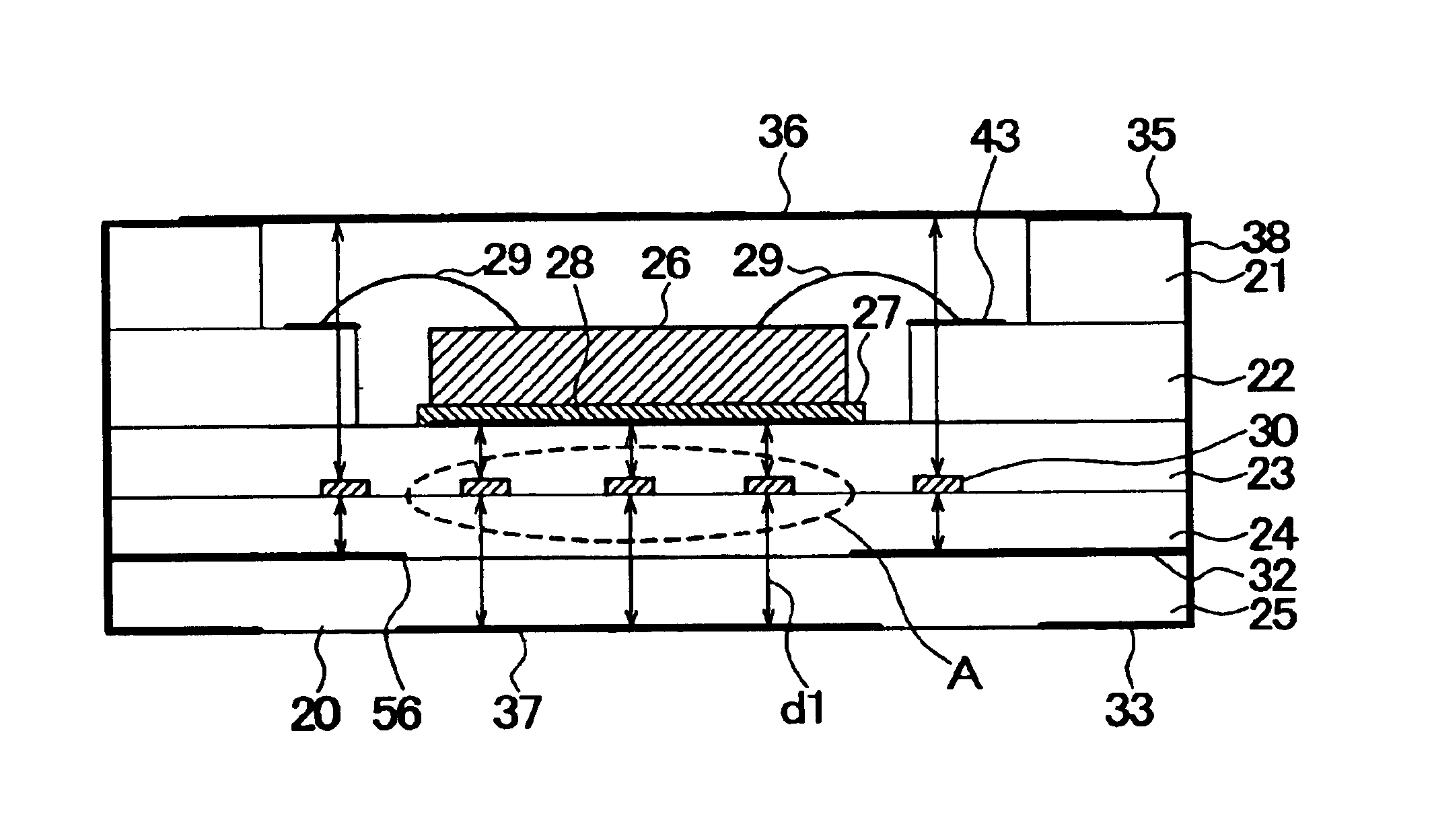
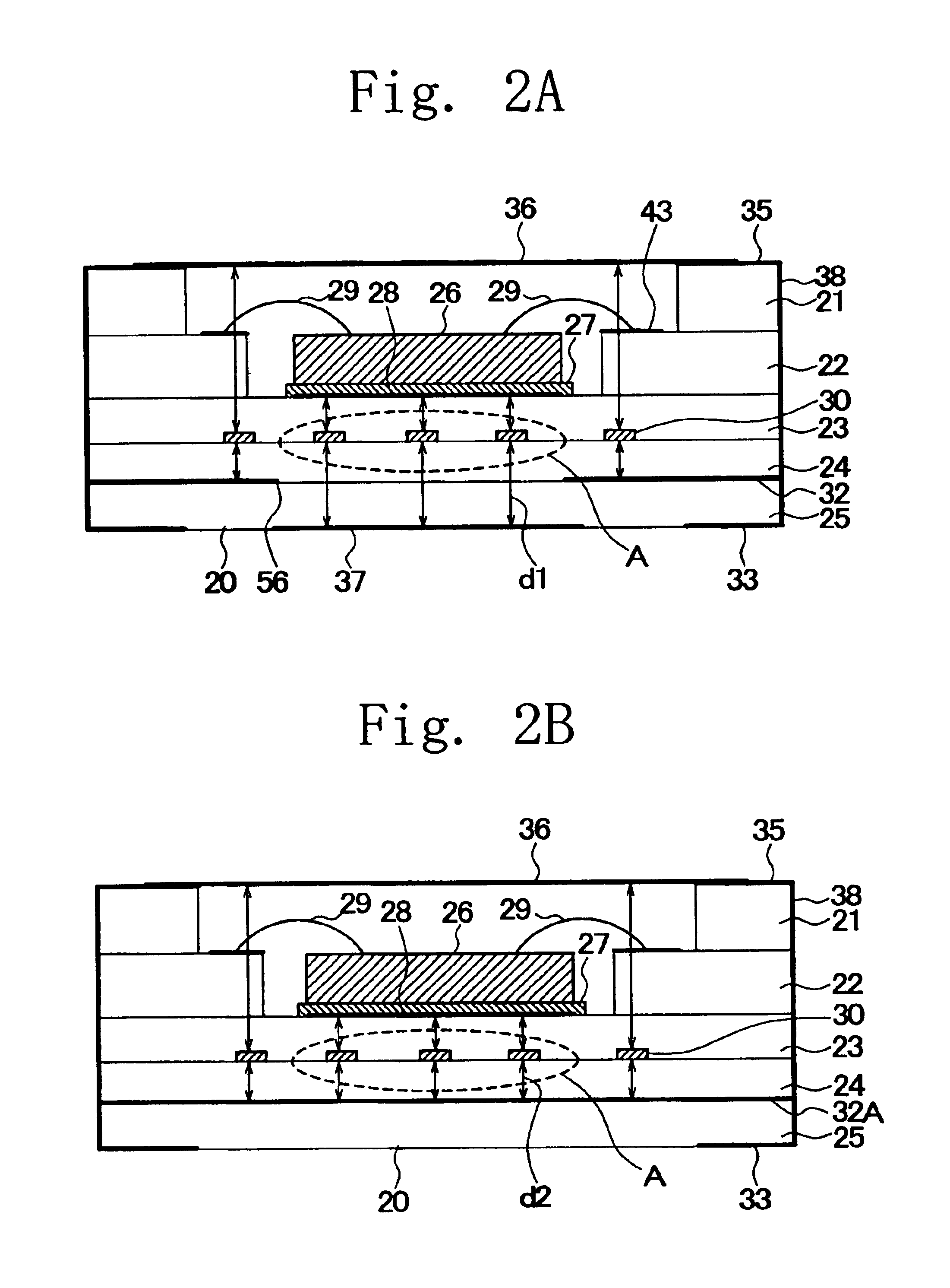
[0048]FIG. 2A is a cross-sectional view of a duplexer according to a first embodiment of the present invention, and FIG. 2B is a cross-sectional view of a duplexer (comparative example) obtained by modifying the duplexer shown in FIG. 2A.

(Structure of the First Embodiment)

[0049]The duplexer shown in FIG. 2A includes a multilayer package 20, a filter chip 26, a phase (impedance) matching line 30, and a cap 36. The multilayer package 20 has five layers 21-25, which are laminated. The layer 21 is a cap mount layer. The layer 22 is a wire bonding pad layer. The layer 23 is a die attachment layer. The layer 24 is a phase matching line pattern layer. The layer 25 is a common ground layer. The layers 21-25 may, for example, be made of alumina having a dielectric constant of about 9.5 or glass ceramics.

[0050]The cap mount layer 21 and the wire bonding pad layer 22 define steps in the package. The space defined by the steps form a cavity for accommodating the filter chip 26. ...

Example

Second Embodiment

[0082]Now, a description will be given of a second embodiment of the present invention with reference to FIGS. 11A and 11B. FIG. 11A is a cross-sectional view of a duplexer according to the second embodiment of the present invention. This sectional view is taken along the line IIa—IIa shown in FIG. 4A on the second embodiment duplexer. In FIGS. 11A and 11B, parts that are the same as those shown in the previously described figures are given the same reference numerals.

[0083]The duplexer of the present embodiment does not have the outer ground pattern 37 that the first embodiment has. Thus, the bottom surface (lower or mount surface) of the common ground layer 25 is arranged as shown in FIG. 11B. The surface of the common ground layer is exposed in the center portion thereof. Rather than the outer ground pattern 37, a ground pattern 66 is formed on a circuit or wiring board 65 such as a printed circuit board and is located in the center of the bottom surface of the c...

Example

Third Embodiment

[0086]FIG. 12 is a cross-sectional view of a duplexer according to a third embodiment of the present invention, in which parts that are the same as those shown in the previously described figures are given the same reference numerals.

[0087]As shown in FIG. 12, an outer ground patter 37B is wider than the outer ground pattern 37 shown in FIG. 2A. The outer ground pattern 37 has a size that substantially covers the whole matching line 30. Thus, the phase matching line 30 is interposed between the cap 36 and the outer ground pattern 37B. In other words, only a pair of ground patterns covers the matching line 30. Even the outermost sectional parts of the matching line 30 are covered by the outer ground pattern 37B rather than an inner ground pattern 32B as indicated by d1. It is therefore possible to more effectively suppress decrease of the characteristic impedance. Since the inner ground pattern 32B does not serve as ground with respect to the matching line 30, it may ...


PUM


Abstract

A duplexer includes a multilayer package, SAW filters that have different band center frequencies and are provided in the multilayer package, and a phase matching line that matches phases of the SAW filters and are provided in the multilayer package. A ground pattern with respect to the phase matching line is provided on a mount surface of the multilayer package.

Description

BACKGROUND OF THE INVENTION[0001]1. Field of the Invention[0002]The present invention generally relates to duplexers using a band-pass type of surface acoustic wave filter (SAW filter), and more particularly, to a duplexer with an impedance matching circuit.[0003]2. Description of the Related Art[0004]In recent years, cellular phones and portable information terminals have spread with the development of mobile communication systems, and manufacturers compete with one another for downsizing and higher performance of these terminals. Some cellular phones operate in both the analog and digital systems and use both a band of 800 MHz to 1 GHz and another band of 1.5 GHz to 2.0 GHz.[0005]Now, there is considerable activity in the development of dual-mode or dual-band cellular phones for improvement in performance. The dual-mode cellular phone operates in the analog and digital systems, or digital TDMA (Time Division Multiplexing Access) and CDMA (Code Division Multiplexing Access). The du...

Claims


Application Information

Patent Timeline
IPC IPC(8): H01P1/213H01P1/20H03H9/00H03H9/64H01L23/12H03H9/10H03H9/25H03H9/72
CPCH01P1/2135H03H9/0576H03H9/725H03H9/6483H03H9/72H01L2224/73265H01L2224/48227H01L2224/48091H01L2224/32225H01L2924/00014H01L2924/00H01L2924/15153H01L2924/16195
Inventor IWAMOTO, YASUHIDEIKATA, OSAMU
Owner TAIYO YUDEN KK
Why Eureka
Try Eureka