
Synthetic aperture radar (SAR) compensating for ionospheric distortion based upon measurement of the group delay, and associated methods

a technology of group delay and synthetic aperture, applied in the field of radar, can solve the problems of difficult to predict the polarization of pulses, the inability to use low frequency space-based sars in mode unavailable to low frequency space-based sars, and the development and performance of low frequency sars are severely limited. to achieve the effect of reducing the ionospheric distortion

Inactive Publication Date: 2005-07-19
NORTH SOUTH HLDG
View PDF14 Cites 79 Cited by
  • Summary
  • Abstract
  • Description
  • Claims
  • Application Information

AI Technical Summary

Benefits of technology

[0014]In view of the foregoing background, it is therefore an object of the present invention to provide a synthetic aperture radar (SAR) that compensates for ionospheric distortions based upon measurement of the group delay, particularly when operating in the VHF / UHF band.
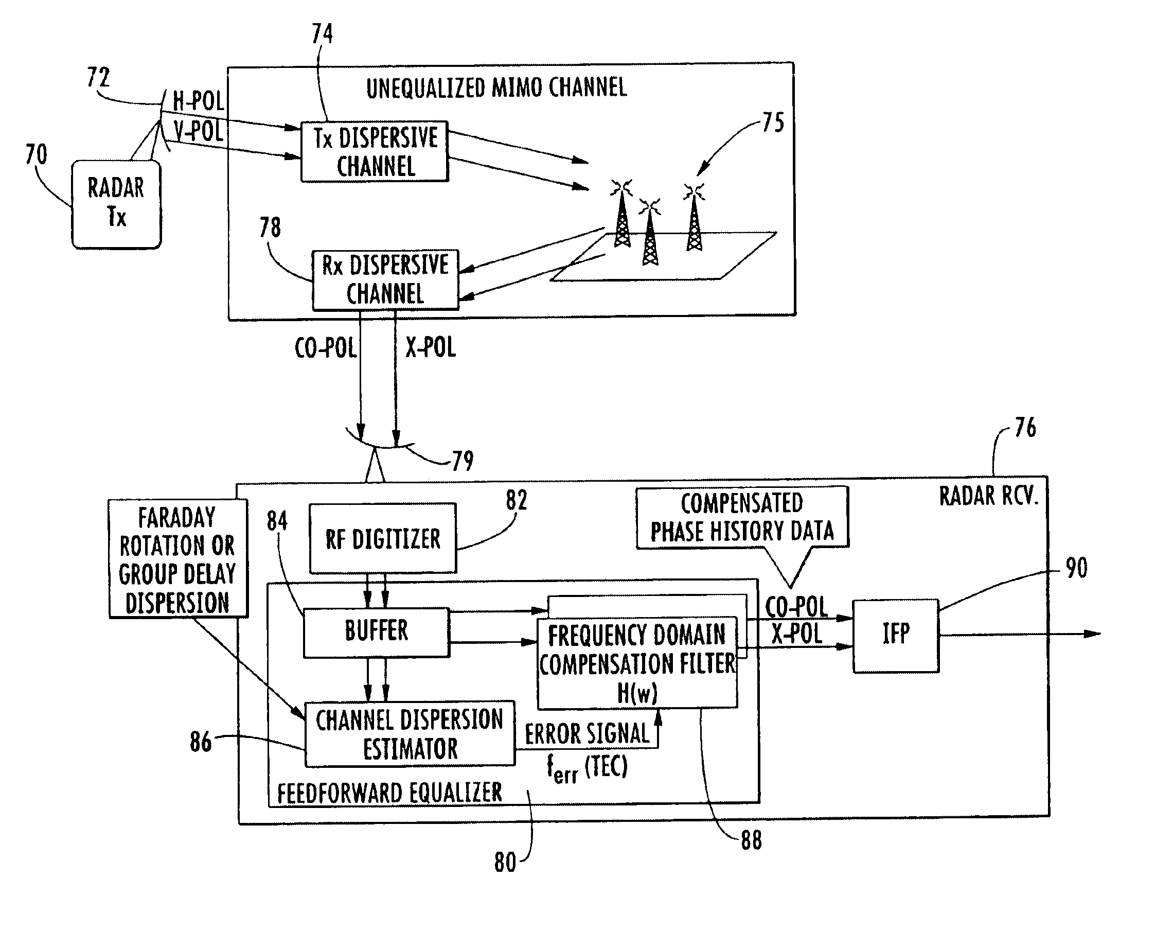
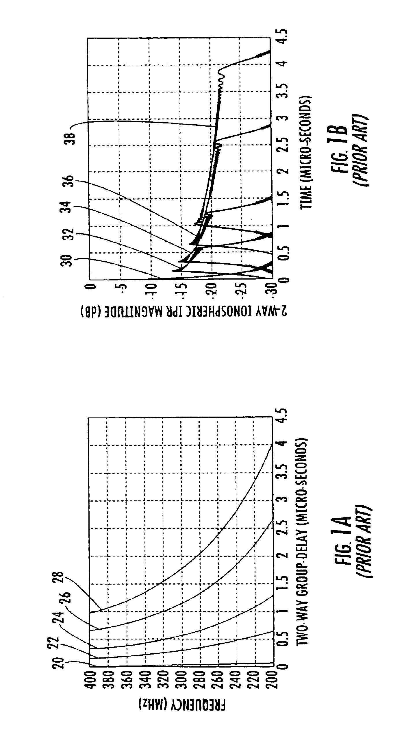
[0015]This and other objects, features, and advantages in accordance with the present invention are provided based upon a multi-input multi-output (MIMO) technique for estimating the effective ionospheric conditions. This MIMO technique is referred to as the group delay (sub-band) approach. The group delay approach is divided into a 1-dimensional (range) approach and a 2-dimensional (range and cross-range) approach. The group delay measures the effective or observed TEC, which is used to reduce the ionospheric distortion.
[0018]The radar receiver may comprises an ionospheric distortion estimator for estimating an individual ionospheric distortion for each received echo pulse based upon a time delay variation versus frequency, and a compensation filter for reducing the ionospheric distortion for each received echo pulse based upon the estimated individual ionospheric distortion associated therewith for providing a compensated echo pulse.
[0025]The radar receiver preferably divides each radar image to be generated into a plurality of sub-images, each sub-image is based upon N consecutive echo pulses with N being less than a total number of echo pulses forming the radar image. The radar receiver may comprise a sub-image ionospheric distortion estimator for estimating an individual ionospheric distortion for each received sub-image based upon a time delay variation versus frequency, and a sub-image compensation filter for reducing the ionospheric distortion from each received sub-image based upon the estimated individual ionospheric distortion associated therewith for providing a compensated sub-image. A sub-image collector collects the compensated sub-images forming the radar image to be generated.

Problems solved by technology

However, to date the development and performance of low frequency SARs has been severely limited by the distortion of the RADAR waveform by the ionosphere.
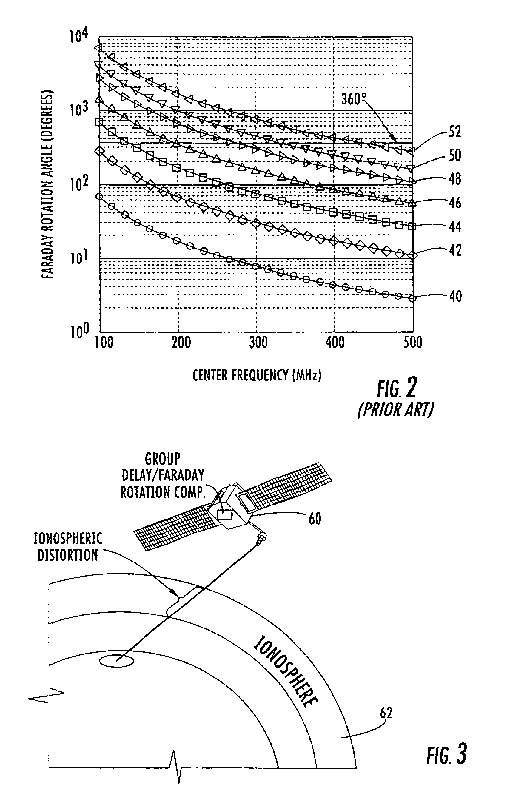
Because of the unknown TEC on the ionospheric path, this rotation is initially unknown, and therefore it is difficult to predict what polarization the pulses will have when they strike an object being imaged.
The Faraday rotation induced by the ionosphere, if left uncompensated, renders this mode unavailable to low frequency space-based SARs.
Even when the rotation is too small to generate a phase ambiguity, it may significantly impact both the incident and reflected field at each scatterer in the scene.
The quality of the prediction is generally insufficient for purposes of a spaced-based SAR, because it is very difficult to obtain measurements with sufficient temporal and spatial proximity to the SAR platform.
Other techniques for direct ionospheric measurement exist (i.e., ionosondes), but all are plagued by the same limitations as the GPS method.
These known data adaptive techniques do not adequately compensate for the spatially varying ionospheric distortion on the transmit pulses and associated echo pulses.
Accuracy is limited by the precision with which the ground-based calibrators can be built, maintained and oriented.
Scene-aided techniques are constrained from a practical standpoint by the need to locate the calibrators in areas where the calibrators can be clearly detected, which may be difficult in certain areas of interest.
Since the ionosphere is not homogeneous and the distortion is spatially varying, assuming a single rotation angle for an entire image is generally not sufficient for high resolution imaging.
Moreover, the article does not address the non-linear phase response of the ionosphere causing time domain distortions.

Method used


Image

  • Synthetic aperture radar (SAR) compensating for ionospheric distortion based upon measurement of the group delay, and associated methods
  • Synthetic aperture radar (SAR) compensating for ionospheric distortion based upon measurement of the group delay, and associated methods
  • Synthetic aperture radar (SAR) compensating for ionospheric distortion based upon measurement of the group delay, and associated methods

Examples


Embodiment Construction

[0047]The present invention will now be described more fully hereinafter with reference to the accompanying drawings, in which preferred embodiments of the invention are shown. This invention may, however, be embodied in many different forms and should not be construed as limited to the embodiments set forth herein. Rather, these embodiments are provided so that this disclosure will be thorough and complete, and will fully convey the scope of the invention to those skilled in the art. Like numbers refer to like elements throughout, and prime notation is used to indicate similar elements in alternative embodiments.

[0048]A multi-input and multi-output (MIMO) adaptive equalization technique for compensating ionospheric distortion imparted on signals used by a synthetic aperture radar (SAR) operating in the VHF / UHF band are discussed in detail below. The MIMO technique estimates the effective ionospheric conditions via observation of the varying group delay induced by the ionosphere, in...


PUM


Abstract

A synthetic aperture radar (SAR) compensates for ionospheric distortions based upon measurement of the group delay, particularly when operating in the VHF / UHF band. The SAR is based upon a multi-input multi-output (MIMO) technique for estimating the effective ionospheric conditions, which is referred to as the group delay approach. The group delay approach is divided into a 1-dimensional (range) approach and a 2-dimensional (range and cross-range) approach. The group delay measures the effective or observed TEC, which is used to reduce the ionospheric distortion.

Description

GOVERNMENT LICENSE RIGHTS[0001]The U.S. Government has a paid-up license in this invention and the right in limited circumstances to require the patent owner to license others on reasonable terms as provided for by the terms of contract No. 03-C-0024, awarded by the U.S. Government.FIELD OF THE INVENTION[0002]The present invention relates to the field of radar, and more particularly, to a synthetic aperture radar (SAR).BACKGROUND OF THE INVENTION[0003]A synthetic aperture radar (SAR) is a moving platform radar mapping technique for generating high resolution images of terrain or targets by taking advantage of the platform's relative velocity with respect to the ground below. SAR imaging techniques are used in both aircraft based and space-based systems. In SAR imaging, the ground is illuminated by transmit pulses that are plane polarized, and the echo pulses scattered back towards the receiver carries information about the nature of the features illuminated. The information availabl...

Claims


Application Information

Patent Timeline
Patent Type & Authority Patents(United States)
IPC IPC(8): G01S7/02G01S7/40G01S13/90
CPCG01S7/025G01S7/4004G01S13/90
Inventor BEADLE, EDWARD R.ANDERSON, PAUL D.RICHTER, STEVEDISHMAN, JOHN F.GANTHIER, EMILE
Owner NORTH SOUTH HLDG
Learn More