Apparatus for measuring specific absorption rate based on near magnetic field for use in radio apparatus

a radio apparatus and specific absorption rate technology, applied in the direction of electrical apparatus construction details, resonant antennas, instruments, etc., can solve the problems of affecting the effect of electromagnetic wave radiated from portable radio apparatus on human bodies, requiring a large amount of time for the measurement of sar, and it is impossible to perform the inspection of sar of portable telephones on a production line using prior art sar measurement methods and apparatuses, and achieves simple method and speed

Inactive Publication Date: 2005-07-19
PANASONIC CORP
View PDF7 Cites 39 Cited by
  • Summary
  • Abstract
  • Description
  • Claims
  • Application Information

AI Technical Summary

Benefits of technology

[0011]An essential object of the present invention is therefore to solve the above-mentioned problems and to provide an SAR measuring apparatus capable of mea...

Problems solved by technology

Accompanying with this, influence of electromagnetic wave radiated from a portable radio apparatus exerted on human bodies has been emerged as a problem.
Therefore, much time is required for the measurement of SAR.
Therefore, it is impossible to perform the inspec...

Method used


Image

  • Apparatus for measuring specific absorption rate based on near magnetic field for use in radio apparatus
  • Apparatus for measuring specific absorption rate based on near magnetic field for use in radio apparatus
  • Apparatus for measuring specific absorption rate based on near magnetic field for use in radio apparatus

Examples


first preferred embodiment

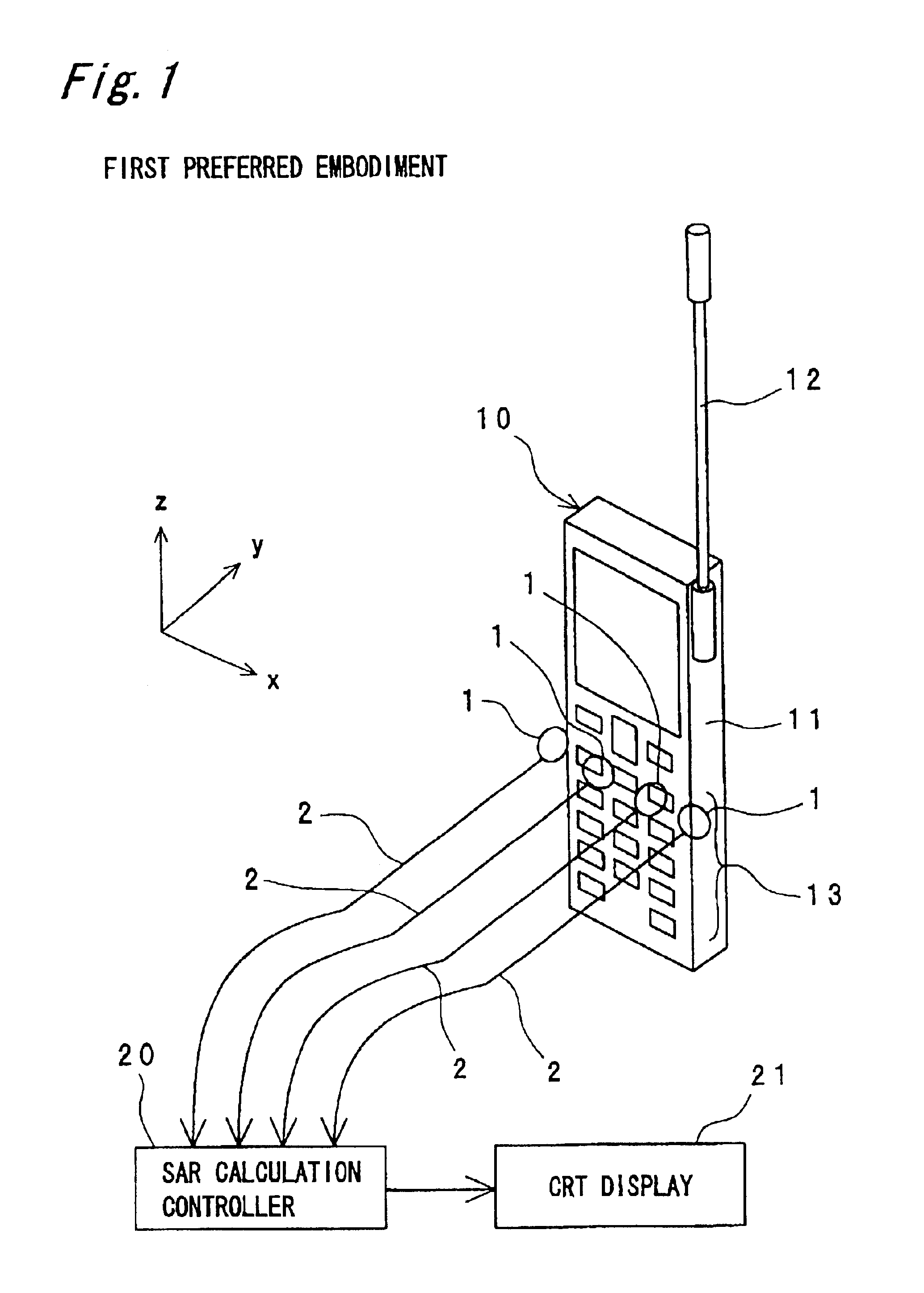
[0089]FIG. 1 is a perspective view and a block diagram showing a structure of an SAR measuring apparatus for measuring SAR of a portable radio apparatus 10 according to the first preferred embodiment of the present invention.

[0090]In the portable radio apparatus 10 of FIG. 1, a whip antenna 12 is mounted so as to extend upward from its casing 11, and a keyboard section 13 is formed in a lower portion of the front surface of the portable radio apparatus 10. As shown in FIG. 1, a plurality of, for example, four magnetic field probes 1 are arranged at regular intervals linearly or aligned in the horizontal direction on the front surface of the keyboard section 13 of the portable radio apparatus 10 so that the probes are located a predetermined distance of adjacency apart from the front surface. It is to be noted that the portable radio apparatus 10 is provided with a built-in flat antenna (not shown) such as an inverted F type antenna, which is arranged on the inside of the casing 11 s...

second preferred embodiment

[0102]FIG. 3 is a perspective view and a block diagram showing a structure of an SAR measuring apparatus for measuring the SAR of a portable radio apparatus 10 according to the second preferred embodiment of the present invention, and FIG. 4 is a sectional view showing an arrangement of magnetic field probes 1-1 to 1-4 of FIG. 3.

[0103]In the present preferred embodiment, there is provided an SAR measuring apparatus of the portable radio apparatus used in the 900 MHz band as one example, each interval of “d” between mutually adjacent magnetic field probes 1 is set to 10 mm (=0.03λ, where λ is the wavelength of the transmission and reception frequency used by the portable radio apparatus 10), and a distance from the tip of the magnetic field probe 1 to the front surface of the portable radio apparatus 10 is set to 10 mm. For each of the magnetic field probes 1, a loop type magnetic field probe provided with a conductor line circular loop at its tip is employed.

[0104]In the present pre...

third preferred embodiment

[0106]FIG. 5 is a perspective view and a block diagram showing a structure of an SAR measuring apparatus for measuring the SAR of a portable radio apparatus 10 according to the third preferred embodiment of the present invention.

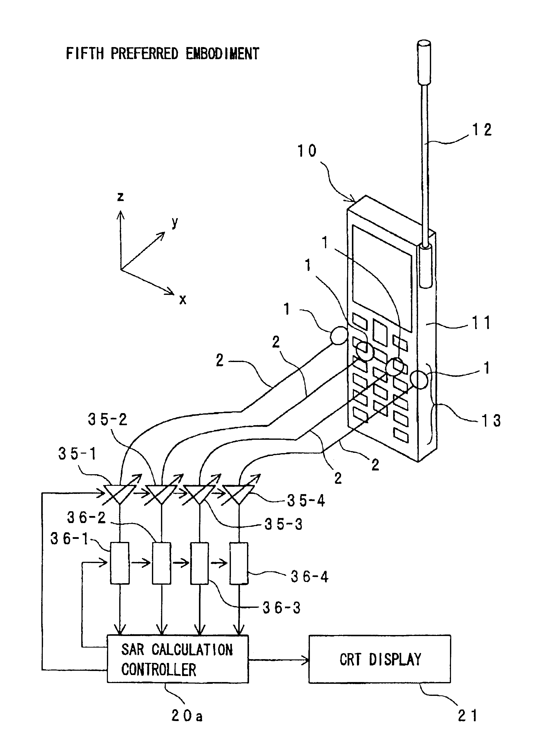
[0107]As shown in FIG. 5, as compared with the first preferred embodiment and the second preferred embodiment, the SAR measuring apparatus of this third preferred embodiment is characterized in that magnetic field probes (hereinafter referred to as dummy magnetic field probes) 1-11 and 1-12 are linearly arranged or aligned so as to be parallel on the outside of the two magnetic field probes located at both ends of four magnetic field probes 1-1 to 1-4. It is to be noted that the two dummy magnetic field probes 1-11 and 1-12 located outside are respectively terminated via respective detection signal cables 2 by non-reflection terminating resistors 3-1 and 3-2 each having the same resistance value as the characteristic impedance of the detection signal cable 2...


PUM


Abstract

In an apparatus for measuring a specific absorption rate (SAR) for use in a radio apparatus, a first near magnetic field of a radio wave radiated from a reference radio apparatus is measured in free space, and an SAR of the radio wave radiated from the reference radio apparatus by using a predetermined phantom according to a predetermined measurement method. A transformation factor α is calculated by dividing the measured SAR by a square value of the measured first near magnetic field, and a second near magnetic field of a radio wave radiated from a radio apparatus to be measured is measured in free space. Then an SAR of the radio wave radiated from the radio apparatus to be measured is estimated and calculated by multiplying a square value of the measured second near magnetic field by the calculated transformation factor α.

Description

BACKGROUND OF THE INVENTION[0001]1. Field of the Invention[0002]The present invention relates to an SAR measuring apparatus for measuring a specific absorption rate (hereinafter referred to as an SAR) based on a near magnetic field, for use in a radio apparatus such as a portable telephone, a portable radio apparatus, or the like.[0003]2. Description of the Related Art[0004]In recent years, portable radio apparatuses such as portable telephones or the like have been widely used. Accompanying with this, influence of electromagnetic wave radiated from a portable radio apparatus exerted on human bodies has been emerged as a problem. An SAR has been used as a general one to provide an index for this influence. It is herein noted that SAR is an electric power absorbed into a unit mass as a consequence of the exposure of a living body of a human being or the like to an electromagnetic field and expressed by the following equation:SAR=(σE2) / ρ  (1).[0005]In this equation, E [V / m] is an elec...

Claims


Application Information

Patent Timeline
IPC IPC(8): G01R29/08H04B1/38
CPCG01R29/0814G01R29/0857H04B1/3838
Inventor OZAKI, AKIHIROOGAWA, KOICHIKOYANAGI, YOSHIOSAITO, YUTAKAKAJIWARA, SHOICHIASAYAMA, YOSHITAKAYAMAMOTO, ATSUSHI
Owner PANASONIC CORP
Why Eureka
Try Eureka