Cross phase modulation suppressing device in wavelength division multiplexing optical transmission system and optical communication system

a technology of optical transmission system and optical communication system, which is applied in multiplex communication, instruments, optical elements, etc., can solve the problems of deteriorating code error rate, delay added cross phase modulation suppressing device, and no function of keeping a relationship between adjacent channels during a period, so as to improve the transmission quality of wavelength multiplexing optical signals

Inactive Publication Date: 2005-07-19
NEC CORP
View PDF15 Cites 27 Cited by
  • Summary
  • Abstract
  • Description
  • Claims
  • Application Information

AI Technical Summary

Benefits of technology

[0011]For the purpose of solving the above conventional problem, an object of the present invention is to provide a cross phase modulation suppressing device in a wavelength division multiplexing optical transmission system and an optical communication system which can suppress the cross phase modulation between channels and improve transmission quality of wavelength multiplexing optical signals, by having a function of giving a delay between channels while keeping the orthogonality of the polarization states between the adjacent channels of the wavelength division multiplexing optical signals which are polarization-interleave multiplexed, from the input through the output by the optical delaying device, in order to realize the two cross phase modulation suppressing method at once; “polarization interleave multiplexing” and “method of giving a delay between each channel in a transmission line”.
[0030]In another preferred construction, the multi / demultiplexer is an AWG (Arrayed Waveguide Grating) capable of splitting and combining the wavelength multiplexing optical signal for every single channel at a low loss.
[0031]In another preferred construction, the multi / demultiplexer is an AWG (Arrayed Waveguide Grating) capable of splitting and combining the wavelength multiplexing optical signal for every single channel at a low loss and the transparent wavelength characteristic thereof is of a plane flat top shape at its top.
[0055]In another preferred construction, the multi / demultiplexer of the multi / demultiplexing means is an AWG (Arrayed Waveguide Grating) capable of splitting and combining the wavelength multiplexing optical signal in every single channel at a low loss.
[0056]In another preferred construction, the multi / demultiplexer of the multi / demultiplexing means is an AWG (Arrayed Waveguide Grating) capable of splitting and combining the wavelength multiplexing optical signal for every single channel at a low loss and the transparent wavelength characteristic thereof is of a plane flat top shape at its top.
[0062]According to the present invention, in an optical fiber transmission line, a wavelength multiplexing optical signal having polarization orthogonality between the adjacent channels is split by the wavelength into a plurality of split optical signals, these split optical signals are led to the optical waveguides of different lengths, and each different delay amount is added to the above signals. The delay-added split optical signals are reflected by the Faraday mirrors, in a state of orthogonalizing the respective polarization states, and again led to the optical waveguides. These several reflected lights are again combined. At this time, the relationship of polarization between the adjacent channels is kept in a state before split by the effect of each Faraday mirror. Since the polarization orthogonality has been kept between the adjacent channels, the signals are supplied to the optical fiber transmission line in an orthogonal state of polarization between the adjacent channels also after the output from the cross phase modulation suppressing device. This can suppress the cross phase modulation between the channels and extremely improve the transmission characteristic of the wavelength multiplexing optical signal.

Problems solved by technology

The most serious problem in the wavelength division multiplexing optical transmission with the narrow channel spacing is an effect of the cross phase modulation that is non-linear interaction between different channels.
The effect of the cross phase modulation causes the waveform distortion by the interaction between difference in arrival time of transferred bits and dispersion of the optical fiber, thus deteriorating the code error rate.
Since the effect of the cross phase modulation becomes stronger according as the channel spacing becomes narrower, the suppression thereof is the most important problem in pursuit of a larger capacity in the future.
The delay added cross phase modulation suppressing device having been proposed so far, however, has no function of keeping a relationship of the polarization states between the adjacent channels during a period from the input through the output.
Therefore, when it is applied to the wavelength division multiplexing optical signals which are polarization-interleave multiplexed, there is a problem such that the polarization states between the adjacent channels are not orthogonal to each other at the output end of the optical delaying device and that the suppression effect of the cross phase modulation becomes smaller by the polarization interleave multiplexing of the signals in a transmission line thereafter.

Method used


Image

  • Cross phase modulation suppressing device in wavelength division multiplexing optical transmission system and optical communication system
  • Cross phase modulation suppressing device in wavelength division multiplexing optical transmission system and optical communication system
  • Cross phase modulation suppressing device in wavelength division multiplexing optical transmission system and optical communication system

Examples


Embodiment Construction

[0084]The preferred embodiment of the present invention will be discussed hereinafter in detail with reference to the accompanying drawings. In the following description, numerous specific details are set forth in order to provide a thorough understanding of the present invention. It will be obvious, however, to those skilled in the art that the present invention may be practiced without these specific details. In other instance, well-known structures are not shown in detail in order to unnecessary obscure the present invention.

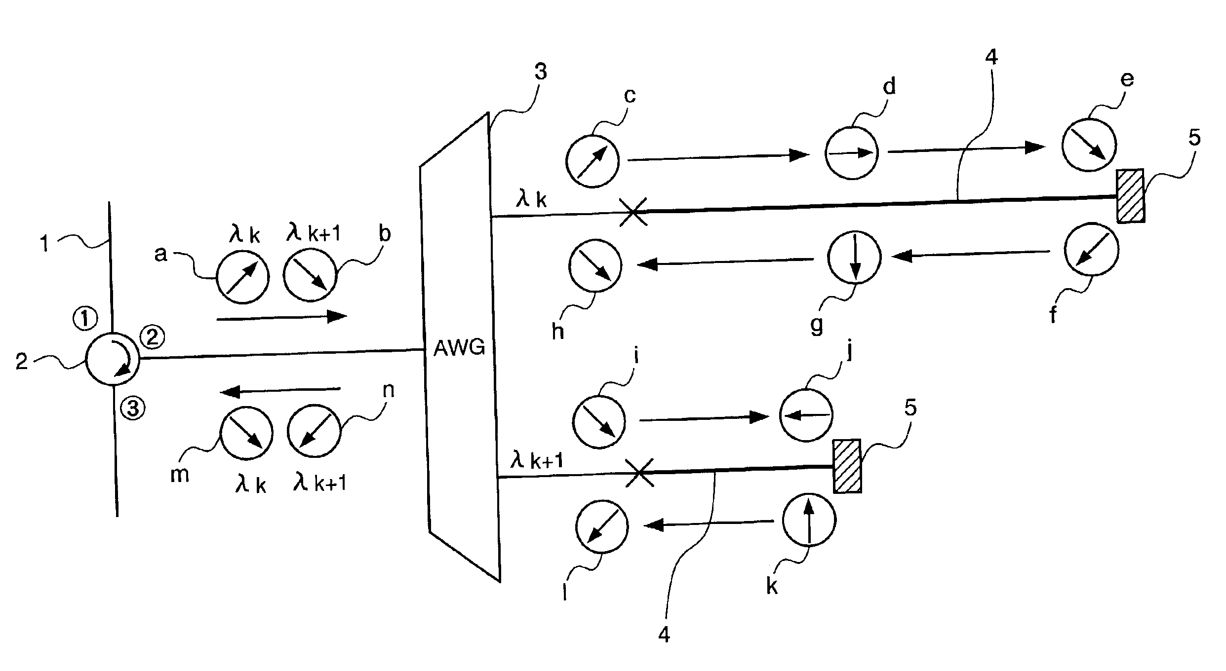
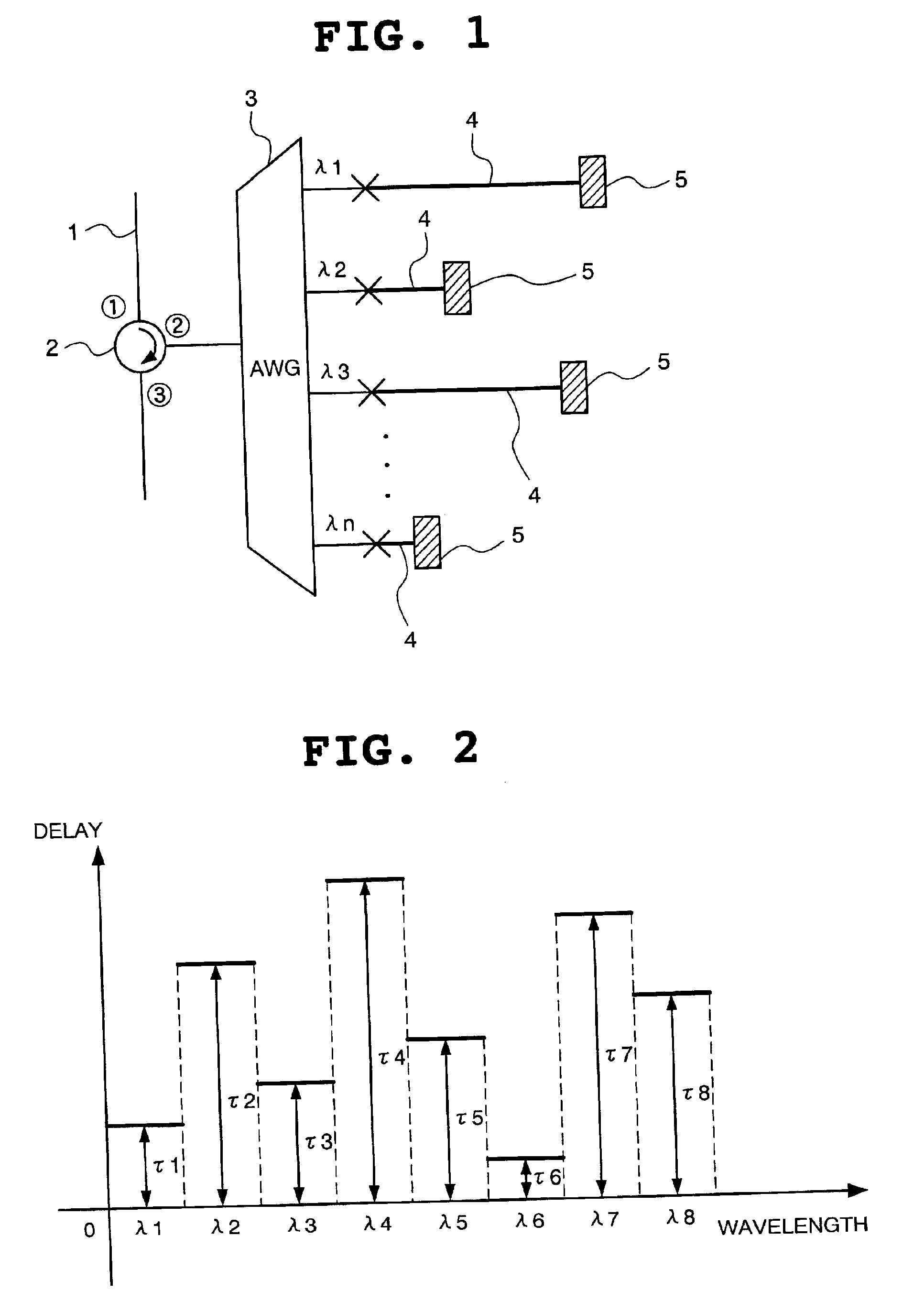
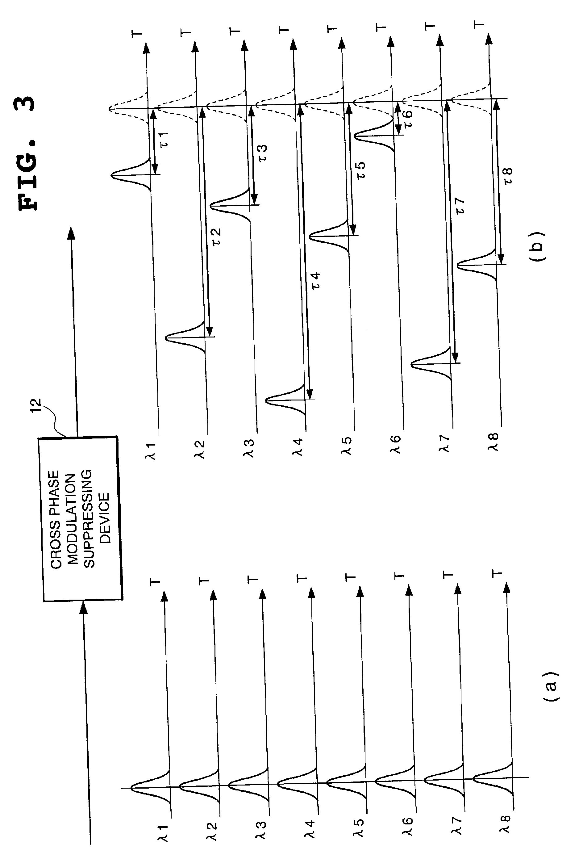
[0085]FIG. 1 is a block diagram showing the structure of a cross phase modulation suppressing device according to one embodiment of the present invention. In FIG. 1, the reference numeral 1 indicates an optical fiber, the reference numeral 2 indicates an optical circulator, and the reference numerals {circle around (1)} to {circle around (3)} of the optical circulator 2 indicate the respective ports. The cross phase modulation suppressing device comprises an ...


PUM


Abstract

According to the cross phase modulation suppressing device of the present invention, the wavelength multiplexing optical signal from an optical fiber having polarization orthogonality between the adjacent channels is split for every channel and the split optical signals are led to delaying optical waveguides of different lengths by the AWG (Arrayed Waveguide Grating) connected to a second port of an optical circulator, and the split optical signals with each delay added are reflected by the Farraday mirrors in polarization states orthogonal to each other and again led to the delaying optical waveguides. The reflected lights are combined by the AWG and supplied to a third port of the optical circulator as the wavelength multiplexing optical signal with orthogonality of polarization states kept between the adjacent channels.

Description

BACKGROUNDS OF THE INVENTION[0001]1. Field of the Invention[0002]The present invention relates to a cross phase modulation suppressing device in a wavelength division multiplexing optical transmission system and an optical communication system, and more particularly to a cross phase modulation repressing device in a wavelength division multiplexing optical transmission system and an optical communication system in which signals are multiplexed so that the polarization states become orthogonal to each other between the adjacent channels.[0003]2. Description of the Related Art[0004]In order to cope with an increase in a communication traffic according to the recent prevalence of the Internet, a main optical fiber adopts a wavelength division multiplexing transmission system for improving the transmission capacity by passing a plurality of channels of different wavelengths within one optical fiber. In this wavelength division multiplexing transmission method, it is necessary to speed u...

Claims


Application Information

Patent Timeline
Patent Type & Authority Patents(United States)
IPC IPC(8): H04B10/18H04J14/02H04B10/2507H04B10/2513H04B10/2557H04J14/00
CPCH04B10/2557H04J14/02
Inventor INADA, YOSHIHISAITO, TOSHIHARU
Owner NEC CORP
Why Eureka
Try Eureka