Welding system and methodology providing multiplexed cell control interface

a control interface and multiplexing technology, applied in the field of welding systems, can solve the problems of increasing costs, reducing control and communication, and requiring bulky and somewhat expensive cabling between the systems, so as to facilitate control and communication, reduce additional welding systems, and reduce costs

Inactive Publication Date: 2005-07-19
LINCOLN GLOBAL INC
View PDF8 Cites 89 Cited by
  • Summary
  • Abstract
  • Description
  • Claims
  • Application Information

AI Technical Summary

Benefits of technology

[0007]The present invention relates to a system and methodology to facilitate control and communications between cell controllers, such as robotic control systems, and one or more welding systems. This is achieved by providing a singular communications interface within the cell controller that is operative in place of a plurality of dedicated and/or analog interface modules associated with the control of one or more welding systems. In this manner, bulky and expensive cables supplied to one or more welding systems, along with a separate interface module per cable and additional welding system can be reduced via the singular communications interface adapted to a control network and associated architecture. Thus, the singular communications interface mitigates cost, and facilitates a more robust control architecture over conventional welding systems (e.g., less cables, wires, modules to maintain). Additionally, scalability is provided since subsequent welders can be readily adapted to an existing welding control system without having to add subsequent int...

Problems solved by technology

As a consequence of the plurality of control signals that are supplied between the cell controller and the welding system, bulky and somewhat expensive cabling between the systems are generally required to route the various signals.
Consequently, manual controls provided as part of the welding process cause operator intervention that generally slows the overall welding process and thereby increases expenses.
Other cabling problems are also created since welders generally operate in substantially harsh environments (e.g., large amounts of electrical noise and/or mechanical disturbances).
Thus, fairly elaborate shielding of the various c...

Method used


Image

  • Welding system and methodology providing multiplexed cell control interface
  • Welding system and methodology providing multiplexed cell control interface
  • Welding system and methodology providing multiplexed cell control interface

Examples


Embodiment Construction

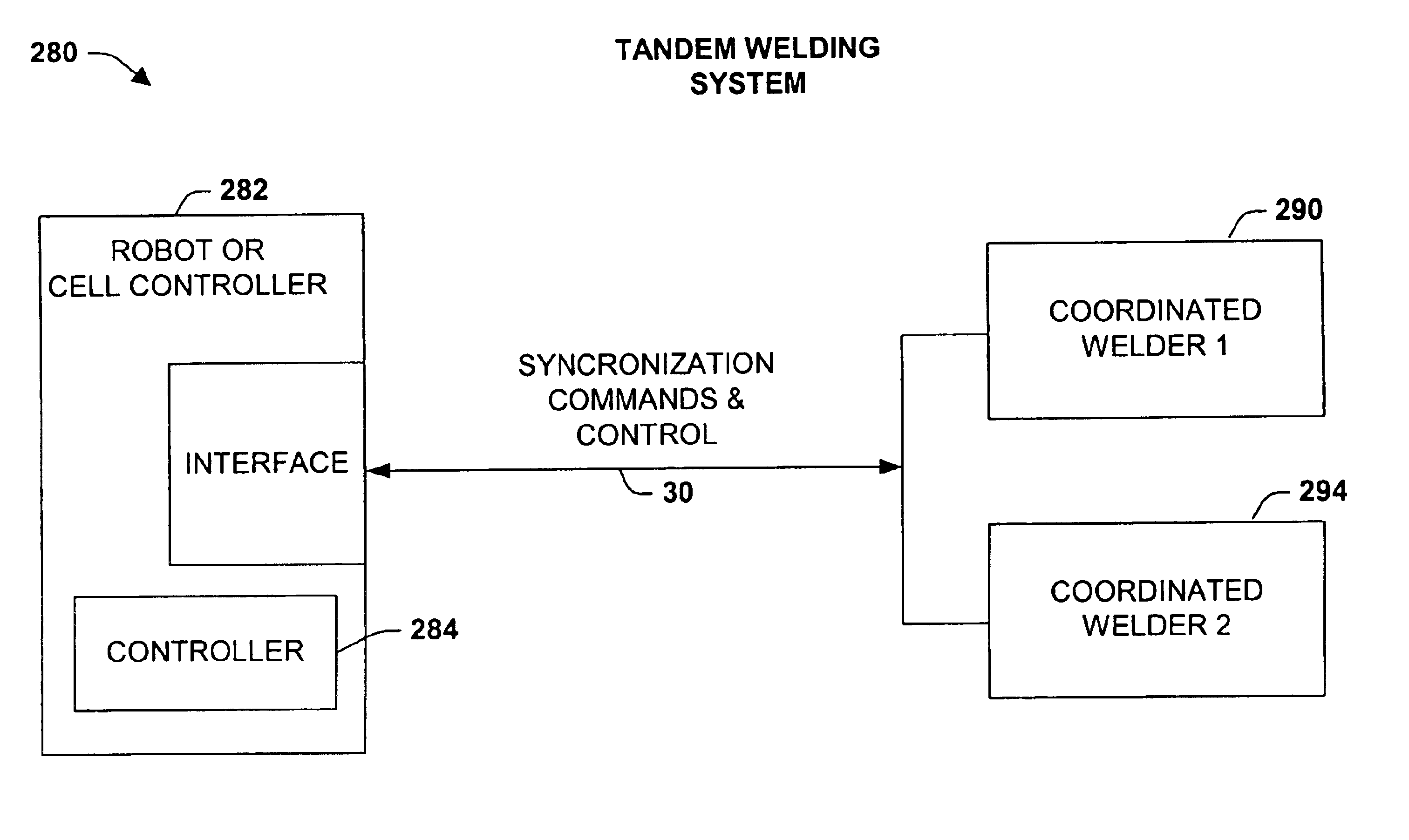
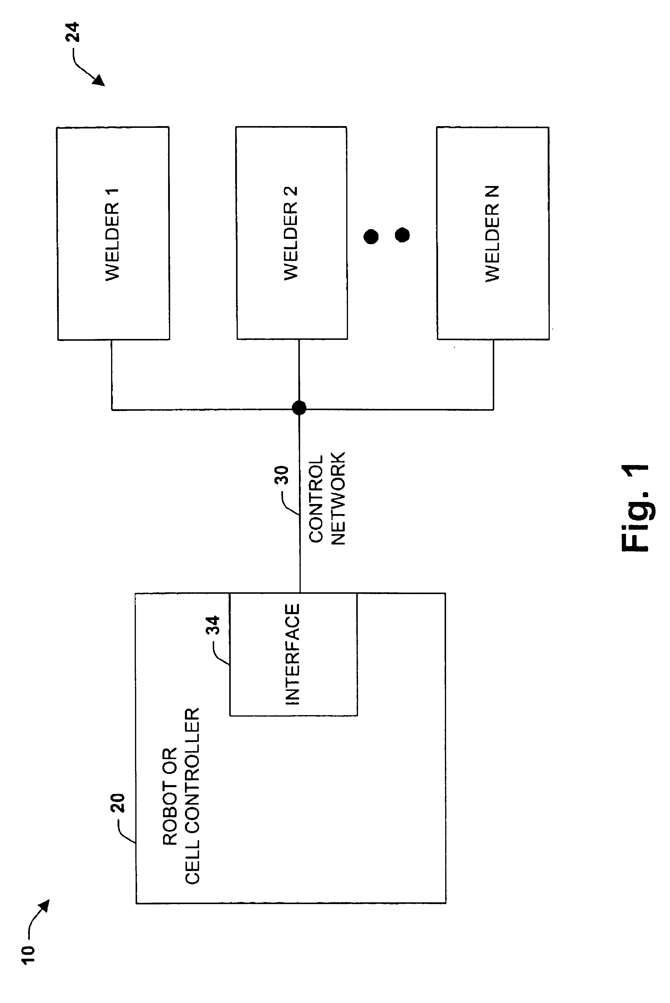
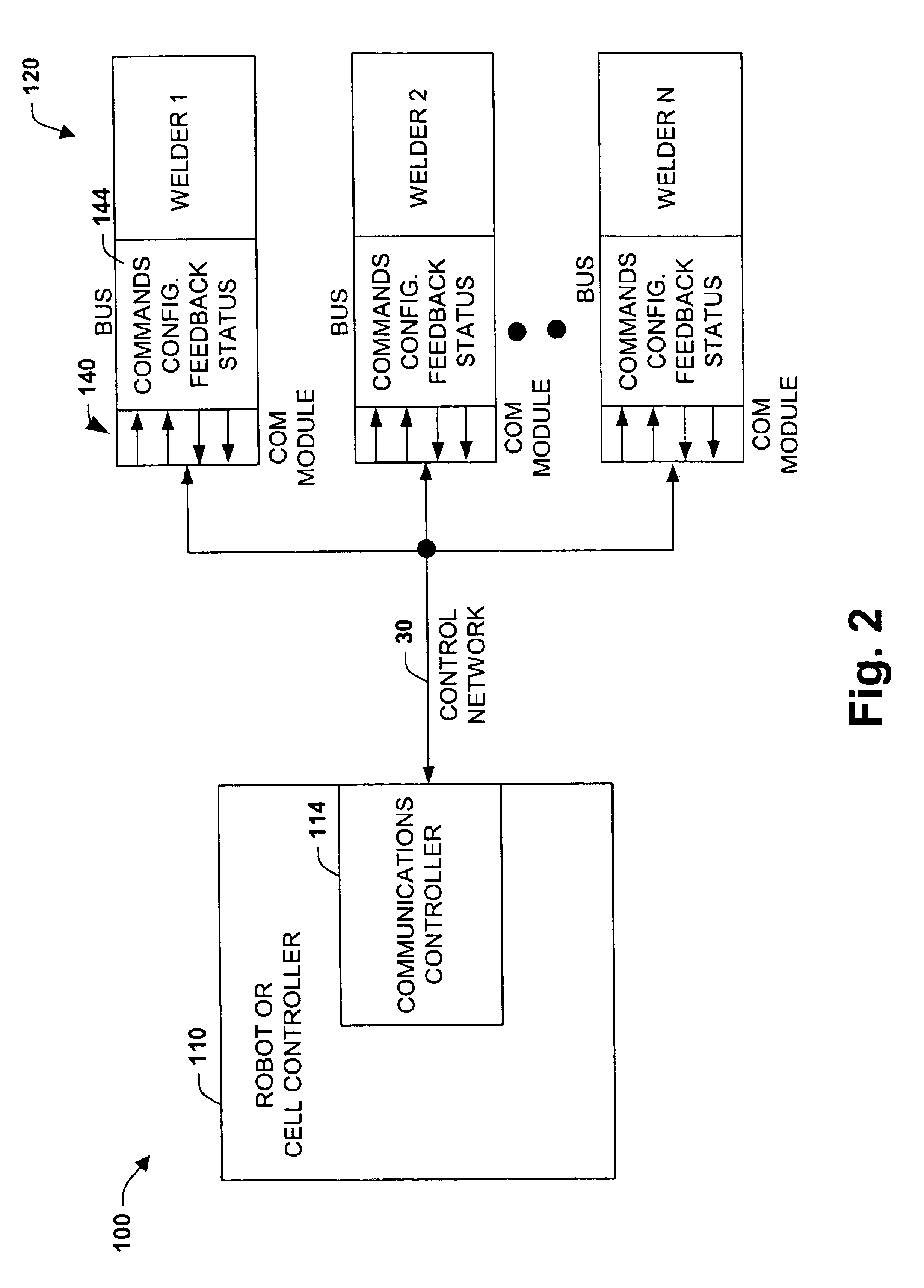
[0020]The present invention relates to a system and methodology to facilitate welding control and communications between one or more welding systems and a cell or robot controller. A communications interface is provided that can utilize a plurality of protocols between the cell controller and the welding systems. For example, a protocol such as Device Net or ProfiBus can be employed to transfer digitized control information to the welding systems and to receive a digitized information response from these systems in the form of feedback and / or other communications. The present invention enables scaling of a current welding system (e.g., adding more welders to present system) without requiring additional interface modules within the cell controller. This can be achieved by employing welding system node addressing within the selected protocol to communicate with one or more welders suitably adapted for such communications. The selected communications protocol and associated interface m...


PUM


Abstract

The present invention provides a welding system and methodology to facilitate communications and control. The system includes a cell controller to control one or more welders over a control network. An interface module associated with the cell controller and the control network communicates with the welders and employs a communications protocol adapted to the interface module to facilitate communications and control between the cell controller and the one or more welders over the control network.

Description

CROSS-REFERENCE TO RELATED APPLICATION[0001]This application is a continuation of U.S. patent application Ser. No. 09 / 925,198, now U.S. Pat. No. 6,697,701, which was filed on Aug. 9, 2001, and entitled WELDING SYSTEM AND METHODOLOGY PROVIDING MULTIPLEXED CELL CONTROL INTERFACE, the entirety of which is incorporated herein by reference.TECHNICAL FIELD[0002]The present invention relates generally to welding systems, and more particularly to a system and method to facilitate communications and control between one or more welding systems and an automated control cell such as a robot.BACKGROUND OF THE INVENTION[0003]Welding systems are often configured in an arrangement, whereby a welder is controlled by a cell or robotic control system. Several of the elements of these systems consist of sending and receiving various control signals that are operative to facilitate the welding process. As an example, analog voltage or current output signals can be employed to control various aspects of ...

Claims


Application Information

Patent Timeline
IPC IPC(8): G05B19/042G05B19/04
CPCG05B19/042G05B2219/24182G05B2219/25208G05B2219/45135
Inventor HILLEN, EDWARD DENNISBLANKENSHIP, GEORGE DARYL
Owner LINCOLN GLOBAL INC
Why Eureka
Try Eureka