Multi-function simplex/prefilmer nozzle

a nozzle and multi-functional technology, applied in the field of spray nozzles, to achieve the effect of convenient and convenient manufacture and assembly, and easy control of efficiency and operation of spray nozzles

Inactive Publication Date: 2005-07-26
PARKER INTANGIBLES LLC
View PDF14 Cites 25 Cited by
  • Summary
  • Abstract
  • Description
  • Claims
  • Application Information

AI Technical Summary

Benefits of technology

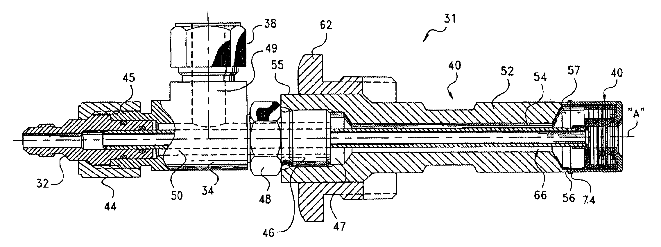
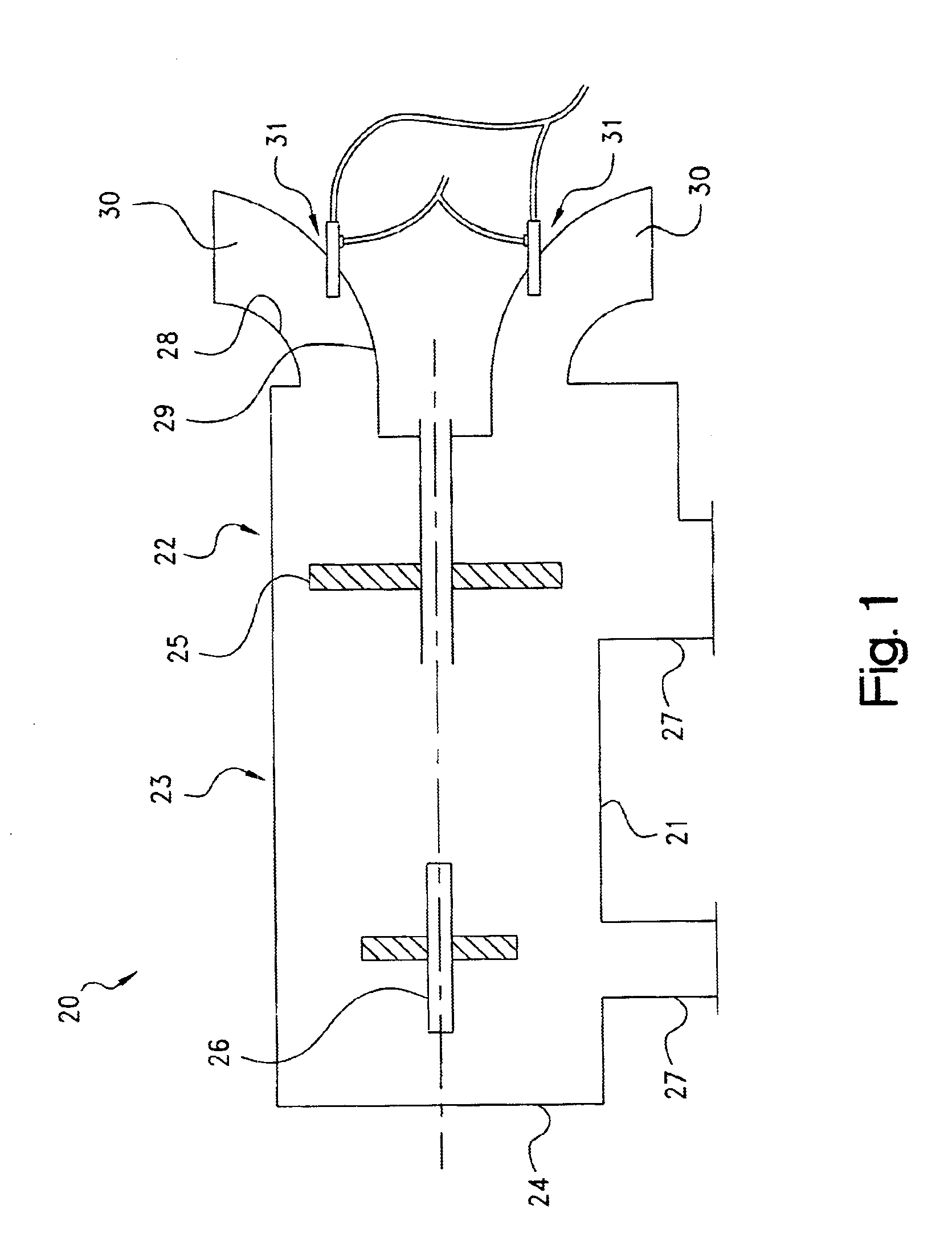
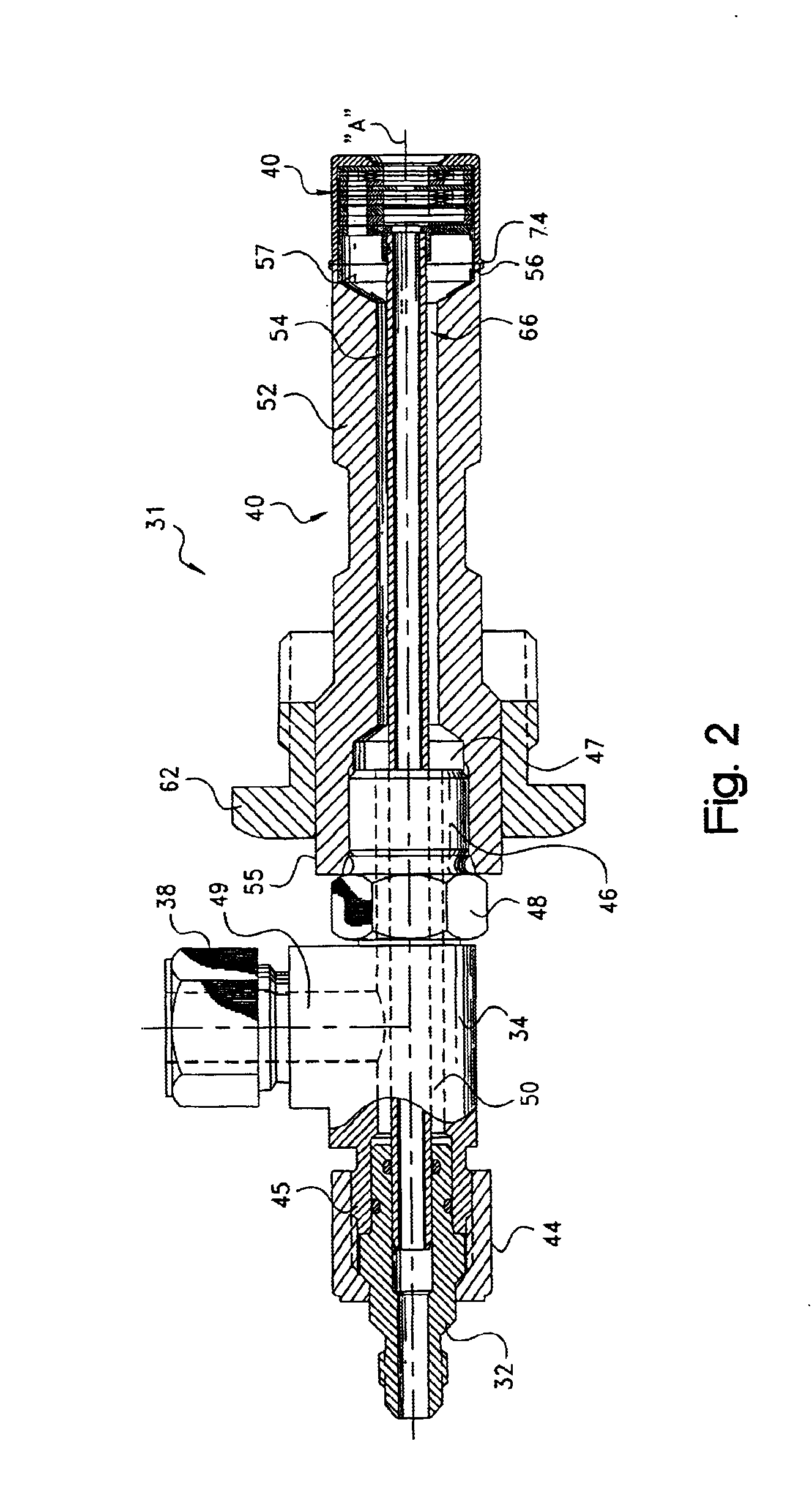
[0009]The present invention provides a novel and unique multi-function spray nozzle for engine applications that is particularly useful i) as a cooling device to introduce fluid into the engine for cooling purposes, and ii) as a cleaning device to introduce a fluid into the engine. The spray nozzle is relatively straightforward to manufacture and assemble, and is replicatable, so that the efficiency and operation of the nozzles can be known and controlled.

Problems solved by technology

It has been a continuing challenge to develop a single spray nozzle which can be used for more than one application, e.g., as a cooling device to introduce fluid into the engine for cooling purposes, and as a cleaning device to introduce fluid into the engine for cleaning purposes.

Method used


Image

  • Multi-function simplex/prefilmer nozzle
  • Multi-function simplex/prefilmer nozzle
  • Multi-function simplex/prefilmer nozzle

Examples


first embodiment

[0084]Closely received within the cover 72 is a plate stack, indicated generally at 80, which defines flow paths through the nozzle tip for the first and second fluids. In the present invention, illustrated in FIGS. 2-4, the plate stack 80 includes a plurality of circular plates 86-96, properly aligned with one another, located in surface-to-surface adjacent relation, and bonded to each other such as by high temperature brazing or other appropriate bonding technique, such as described in U.S. Pat. No. 6,321,541, which is incorporated herein by reference. Each plate in the plate stack, as will be described below, preferably includes a portion of at least one of the flow paths.

[0085]Referring now to FIGS. 5A-15B, each plate 86-96 in the plate stack is illustrated. By properly aligning and locating the plates in adjacent, surface-to-surface relation, circular passages as at 99 are provided through the plates 86-88 (FIGS. 5A-7A) of the stack generally along the central axis of the nozzl...

second embodiment

[0096]Referring now to FIG. 16, the present invention is shown where the plate stack 80 defines a prefilming airblast nozzle. To this end, referring now also to FIGS. 17A-29B, a series of circular plates 130-142 are properly aligned and located in surface-to-surface adjacent relation with one another. Plates 130-142 are in most ways similar to plates 86-96 in FIGS. 5A-15B, in that they are preferably etched, and provide flow paths for the fluids through the nozzle tip.

[0097]Specifically, axial, generally circular passages as at 149 are provided through the plates 130-132 (FIGS. 17A-19B) of the stack generally along the central axis of the nozzle, which are then connected through lateral passages as at 150 in plate 132 (FIG. 19B), to second axial passages as at 151 in plates 133-135 (FIGS. 20A-22B), generally parallel / offset from the central axis. The second axial passages 151 feed a series of lateral passages as at 153 in plates 134 and 135 (FIGS. 21A-22B), which non-radially (tange...


PUM


Abstract

A multi-function spray nozzle for engine applications useful as a cooling device to introduce a fluid into the fluid stream of the engine, and as a cleaning device to introduce a fluid to clean internal components of the engine. The nozzle includes a multi-layered arrangement of etched plates defining flow paths for the first and second fluids. Non-radial feed slots direct the first fluid into a cylindrical swirl chamber. The swirling fluid exits the swirl chamber through a spray orifice or a prefilmer, depending on whether the nozzle is configured as a simplex or prefilmer nozzle. Other non-radial feed slots direct the second fluid inward, downstream of the first fluid, to create a fine dispersion of droplets for fluid stream cooling purposes. During cleaning, only the first fluid is introduced through the nozzle, which results in a larger droplet size suitable for cleaning purposes of the internal components of the engine.

Description

CROSS-REFERENCE TO RELATED CASES[0001]The present application claims the benefit of the filing date of U.S. Provisional Application Ser. No. 60 / 365,079, filed Mar. 15, 2002; and U.S. Provisional Application Ser. No. 60 / 434,170, filed Dec. 17, 2002, the disclosures of which are expressly incorporated herein by reference.FIELD OF THE INVENTION[0002]The present invention relates generally to spray nozzles, and more particularly, to spray nozzles useful for introducing one or more fluids into engines, and particularly into gas turbine combustion engines.BACKGROUND OF THE INVENTION[0003]Gas turbine engines typically include a compressor section for compressing inlet air, a combustion section for combining the compressed air with fuel and combusting the fuel, and a turbine section where the energy from the hot gas produced by the combustion of the fuel is converted into work. The exhaust gas from the turbine section can also be used to achieve thrust or as a source of heat and energy.[000...

Claims


Application Information

Patent Timeline
Patent Type & Authority Patents(United States)
IPC IPC(8): B05B7/10B05B7/02B05B7/04F02C3/20F02C3/30F23L7/00
CPCB05B7/0458B05B7/10F02C3/305F23L7/002F23D2900/00002
Inventor MANSOUR, ADEL B.BUCA, PETER V.HARVEY, REX J.AIKEN, KIM LDUNCAN, JAMES F.
Owner PARKER INTANGIBLES LLC
Why Eureka
Try Eureka