
Cold heat reused air liquefaction/vaporization and storage gas turbine electric power system

Inactive Publication Date: 2005-07-26
MITSUBISHI HITACHIPOWER SYST LTD
View PDF17 Cites 64 Cited by
  • Summary
  • Abstract
  • Description
  • Claims
  • Application Information

AI Technical Summary

Benefits of technology

[0006]A second object of the present invention is to provide an energy storage gas-turbine electric power generating system having a high energy storage efficiency.
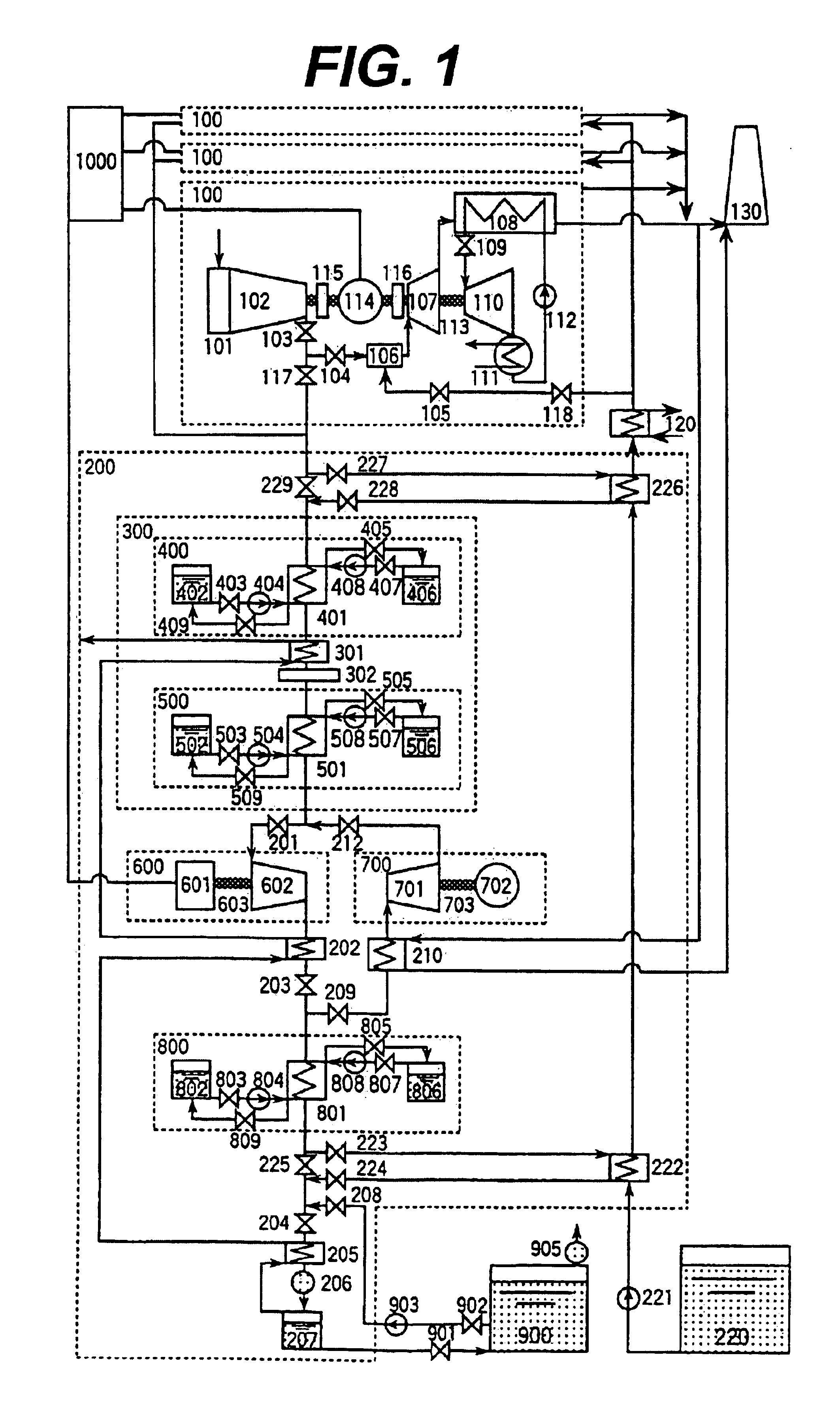
[0008]According to the present invention described above, since the air in a liquid state (liquid air) is pressurized and then vaporized to drive the expansion turbine by the vaporized air, there is an effect that the generating power of the system is increased as a whole. In other words, the power (electric power) required for compressing (pressurizing) the liquid is negligible compared to the power required for compressing the gas. That is, the power required for the pressurizing unit is nearly negligible, and on the other hand, a large amount of electric power can be obtained from the expansion turbine. Further, since the amount of electric power obtained by the expansion-turbine generator is added in addition to the electric power obtained by the gas-turbine generator, the generating power of the system is increased as a whole.
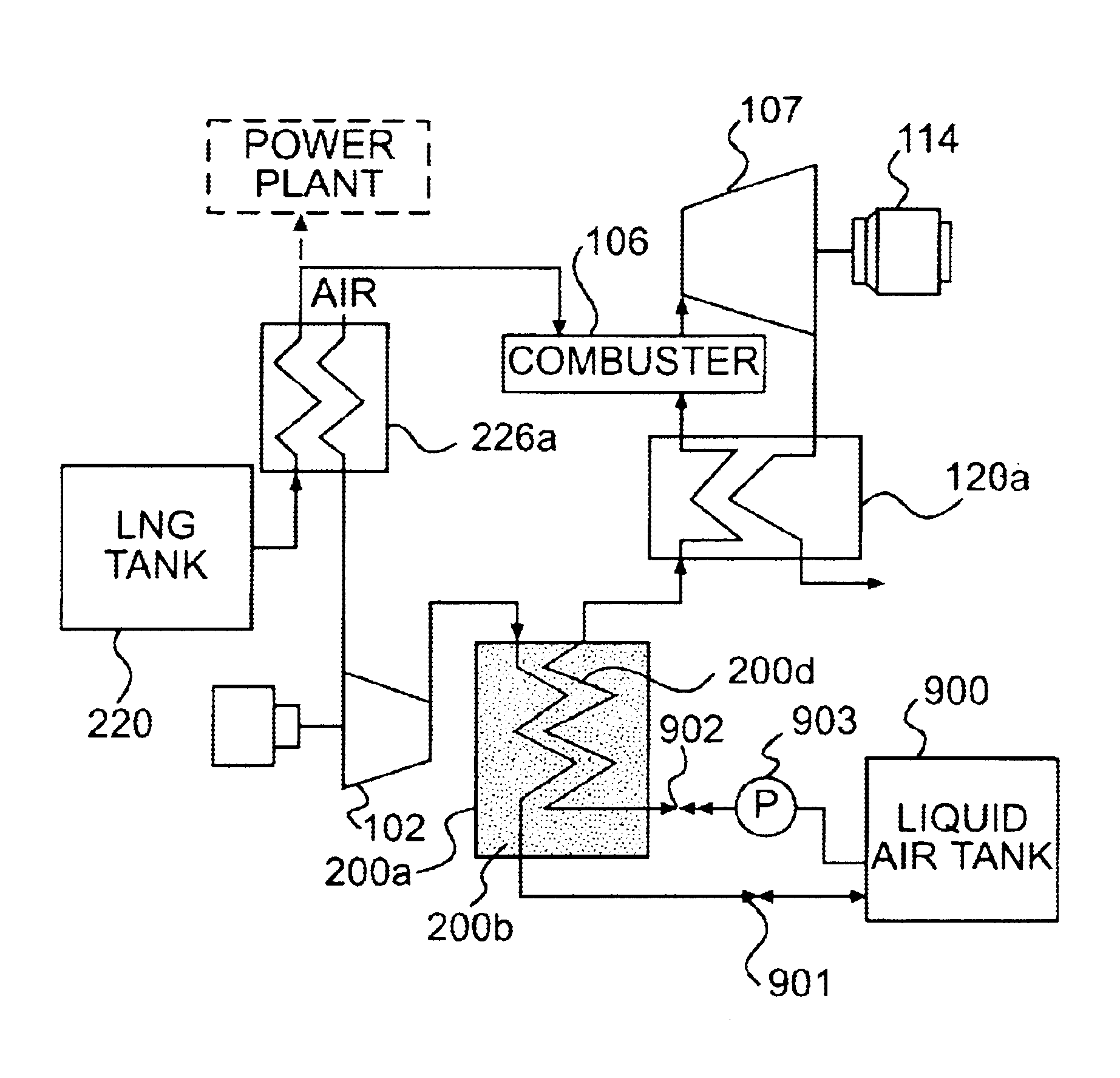
[0010]According to the present invention described above, since cold energy of the air cooled by expanding in the expansion unit is recovered when the liquid air is vaporized to be supplied to the combustor and the air compressed by the compressor is cooled using the cold energy when the liquid air is produced, there is an effect in that the energy storage efficiency is increased. Hereinafter, whenever the term cold heat is used, reference is being made to cold energy. The production ratio of the liquid air produced by the liquefaction / vaporizing facility of the energy storage gas-turbine system in accordance with the present invention can be increased to 80% from 20% in the conventional energy storage gas-turbine system.
[0012]According to the present invention described above, since the liquid air storage tank is arranged inside the cold heat regenerator, heat flow from the outside into the liquid air storage tank is interrupted by the cold energy regenerator and thereby there is an effect in that the energy storage efficiency can be increased by suppressing temperature increase of the liquid air stored in the liquid air storage tank. Further, since the heat storing medium of the cold energy regenerator is solid and accordingly a tank for storing the heat storing medium or the like is not necessary, there is an effect in that the liquefaction / vaporizing facility is simplified. Furthermore, since the heat storing medium of the cold energy regenerator is solid, there is an effect that the supporting structure of the liquid air storage tank can be improved when the liquid air storage tank is installed inside the cold energy regenerator.
[0014]According to the present invention described above, since the air compressed by the compressor is cooled using the cold energy of the fuel (for example, LNG stored in a liquid phase) to be supplied to the combustor, there is an effect in that the energy storage efficiency can be improved. That is, in a conventional gas-turbine electric power generating plant, the very low temperature fuel stored in liquid phase is heated and vaporized by exchanging heat with sea water to be supplied to the combustor. In the energy storage gas-turbine system, the cold energy of the fuel having been disposed to sea water is used for cooling the air and accordingly the energy storage efficiency is increased by the amount of the cold energy of the fuel having been disposed to sea water.

Problems solved by technology

Demand for electric power during daytime on a weekday is very large compared to demand for electric power during nighttime.
Since the period necessary for the maximum electric demand is as short as around ten days in the summer, it is uneconomical to install a large scale electric generating facility for coping with solely this problem.
On the other hand, there remain few sites capable of constructing a scale pump-up hydraulic power station in certain areas, and accordingly a large capacity energy storage method of another type is required to be developed.
However, in the system of Japanese Patent Application Laid-Open No.4-132837, the energy storage efficiency (a ratio of an electric power for obtaining the liquid fluid such as liquid air or liquid oxygen to an electric power generated by the plant) is not so high.

Method used


Image

  • Cold heat reused air liquefaction/vaporization and storage gas turbine electric power system
  • Cold heat reused air liquefaction/vaporization and storage gas turbine electric power system
  • Cold heat reused air liquefaction/vaporization and storage gas turbine electric power system

Examples


first embodiment

[0029]The thermal energy given to air in a combustor is converted into mechanical energy (rotation energy) by a gas turbine and a steam turbine corresponding to respective suitable temperature ranges, and converted into electric energy by motor generators. By doing so, the thermal efficiency becomes as high as 48%. However, when the inside of the gas turbine system (mainly, the compressor and the gas turbine) is examined, there is a possibility to increase the electric generating power. For instance, in a gas turbine system of generating power of 150 MW class, although the mechanical energy generated by the gas turbine is 300 MW which is twice as large as the electric generating power, nearly one-half of the mechanical energy is consumed as the power of the compressor. In order to obtain steam in the steam turbine system (mainly, a heat recovery steam generator and a steam turbine and a feed water pump), condensed water in liquid state is pressurized by the feed water pump. The elec...

second embodiment

[Second Embodiment]

[0086]A second embodiment of an energy storage gas turbine system in accordance with the present invention will be described below.

[0087]This embodiment is characterized by that the heat medium is solid. That is, the heat medium tanks in the first embodiment in accordance with the present invention are replaced by cold heat regenerators. Further, the present embodiment is characterized by that the liquid air storage tank is installed inside the cold heat regenerator.

[0088]FIGS. 4A, 4B and FIG. 5 show the construction of an embodiment of a cold heat regenerator of an energy storage gas-turbine electric power generating system in accordance with the present invention. In FIGS. 4A and 4B, the reference character 30 indicates a steel pipe, the reference character 31 indicates a header, and the reference character 33 indicates a solid heat medium.

[0089]The mechanical system of the present embodiment is the same as in the first embodiment except that the high temperatur...

third embodiment

[Third Embodiment]

[0104]A third embodiment of an energy storage gas turbine electric power generating system will be described below.

[0105]In general, when a gas having the same weight is compressed, power required to compress the gas becomes small as the temperature of the gas supplied to the compressor (the inlet side of the compressor) is lower and as the volume of the gas is smaller. That is, when air is compressed using a compressor having one stage, temperature of the air is increased in the compression process. Therefore, when the air in the middle of the compression process in the compressor is once cooled and then further compressed, the power of the compressor can be reduced compared to the case without the cooling. The present embodiment is characterized by that the compressor is constructed in multistage (for example, three-stage) and the air in the middle of compression process is cooled.

[0106]FIG. 8 is a diagram showing an embodiment of a mechanical system of a gas tur...


PUM


Abstract

An energy storage gas-turbine electric power generating system includes a liquid air storage tank for storing liquid air, a vaporizing facility for vaporizing the liquid air stored in the liquid air storage tank, a combustor for generating a combusted gas by combusting the air vaporized by the vaporizing facility and a fuel, a gas turbine driven by the combusted gas generated in the combustor, and a gas-turbine generator connected to the gas turbine for generating electric power. The system further includes a pressurizing unit for pressurizing the liquid air stored in the liquid air storage tank up to a pressure higher than a pressure of air supplied to the combustor to supply the liquid air to the vaporizing facility, an expansion turbine driven by expanding the air vaporized by the vaporizing facility and an expansion-turbine generator connected to the expansion turbine for generating electric power.

Description

[0001]This is a Continuation-in-Part (CIP) application of U.S. Ser. No. 09 / 765,338 filed Jan. 22, 2001, now abandoned, which is a divisional of U.S. Ser. No. 08 / 991,608 filed Dec. 16, 1997, now abandoned, the entire disclosures of which are hereby incorporated by reference.BACKGROUND OF THE INVENTION[0002]Demand for electric power during daytime on a weekday is very large compared to demand for electric power during nighttime. Therefore, in the past, a nuclear power station and a steam power station using a steam turbine are always operated regardless of daytime and nighttime, and a hydraulic power station and a thermal power station using a gas turbine (for example, a combined cycle power station) are operated only during daytime. Further, electric demand and electric supply are balanced by pumping up water to a reservoir to a high level by driving a pump using surplus power during nighttime (power left over at the nuclear power station and the steam power station) to store as pote...

Claims


Application Information

Patent Timeline
IPC IPC(8): F02C6/14F02C6/00F25J1/02F25J1/00
CPCF02C6/14F25J1/0012F25J1/004F25J1/0045F25J1/0221F25J1/0251F25J1/027F25J2205/24F25J2210/62F25J2230/08F25J2230/22F25J2230/30F25J2230/40F25J2240/70F25J2240/82F25J1/0228F25J2235/02
Inventor WAKANA, HARUMICHINO, KOICHIYOKOMIZO, OSAMU
Owner MITSUBISHI HITACHIPOWER SYST LTD
Learn More