
Sealing mechanism for vessel and cap to be used in the mechanism

a sealing mechanism and vessel technology, applied in mechanical devices, internal fittings, transportation and packaging, etc., can solve the problems of inability to fix a sealing check member (usually called as a cut-ring), fixed portion itself can be put off the vessel, and cost to make the structure, etc., to achieve effective collection and recycling

Inactive Publication Date: 2005-07-26
MASASHI TAKAHASHI +1
View PDF9 Cites 73 Cited by
  • Summary
  • Abstract
  • Description
  • Claims
  • Application Information

AI Technical Summary

Benefits of technology

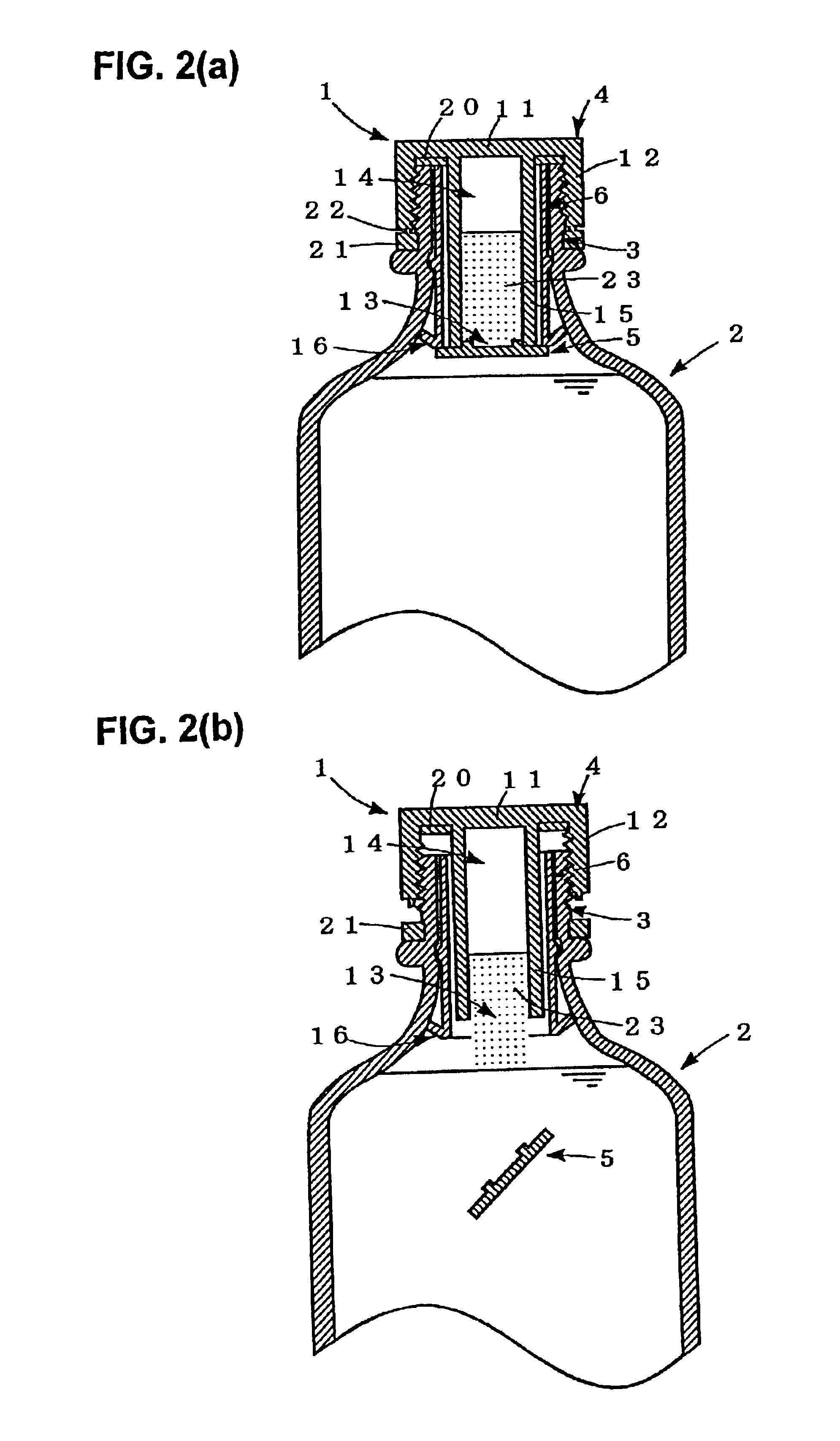
[0027]Regarding the sleeve, it is prevented from being pulled out from the vessel by the sepal portion having outer diameter larger than inner diameter of the opening portion, and also the sepal portion has flexibility to passes the inner diameter bending so as to avoid backward moving. Then, because of its structure, it is able to be inserted inside the vessel easily but not to be pulled out from the vessel after inserting. Therefore, according to the cap, even if the plug portion and the sleeve are united as one body, it is possible to be screwed easily and directly to the vessel. Then, according to the sealing mechanism using the cap, the cap to seal the vessel where the raw material and the liquid to be mixed are separately preserved is able to be fixed easily and directly to the vessel.
[0028]Further, according to the cap, as the receiving chamber is formed by the cylindrical wall projecting from the top board and the opening mouth at under end face is sealed by the seal plug, its inside is completely shut from the outside air. Then, according to the sealing mechanism using the cap, it is possible to prevent raw material preserved in the receiving chamber from deterioration due to the oxygen in the air or other phenomena.
[0031]To do like this, as engaging strength of the sleeve to the vessel is increased and effect of avoiding to be pulled out is enhanced, the receiving chamber is more surely opened.
[0033]To do like this, after the seal plug separates from the cylindrical wall, the sleeve is prevented from dropping inside the vessel with the seal plug. Especially, this flange is effective in case the sepal portion of the sleeve engages to a shoulder portion positioning at bottom of the opening portion and whose inner diameter is enlarged. In case of having the circular protruding portion engages with the circular groove or in case the sepal portion stays in the opening portion and engages there, the sleeve is prevented from being pulled out the vessel or dropping inside the vessel by the circular groove or the sepal portion. However, in case only engaging strength of the circular protruding portion or the sepal portion to the opening portion is not enough to avoid dropping off, the flange may be formed to surly avoid dropping off.
[0035]To do like this, the seal plug separated from the cylindrical wall is prevented from dropping inside the vessel.
[0037]To do like this, the vessel is collected and recycled effectively.

Problems solved by technology

Therefore, it is impossible to fix a sealing check member (usually called as a cut-ring) to be obligatory put in purpose of maintaining hygiene.
However, in case the movable portion to seal the vessel is screwed and fixed on the fixed portion, there is a problem that the fixed portion itself can be put off the vessel in spite of the cut-ring engaging on the fixed portion.
Therefore, because the structure is brought to be complex, there is a problem of cost to make structure wherein the fixed portion is screwed on the vessel.
Further, as being such a complex structure, there is a problem that the cost tends to be high because of requiring constructing processes and so on.
However, as the second prior means requires a vessel of special shape having a structure to open the receiving chamber, vessels widely distributed in market are not able to be used and there is a problem that cost of the vessel is increased.
Namely, when the cap seals the vessel the packing has to be inserted being rotated, and there is a problem that the sealing process is to be extremely difficult.
Further, according to the third prior means, it is impossible to tightly fix the inner plug to the top wall which plug has to be separated from the top wall only by rotation of the cap, and the receiving chamber formed by the inner plug and the top wall is not able to be sealed completely.
Therefore, it is difficult to completely prevent raw material reserved in the receiving chamber from oxidation, brownishness, aging and deterioration caused by oxygen in the air.
Further more, according to the fourth prior means, in case where the rim portion of the bottom plate of the inner cap is made to bent downward too much by production error and so on, there is a fear that the inner cap is stuck in the opening portion as it moves upwardly with the cap when the vessel is opened and plugs the vessel without it drops from there.

Method used


Image

  • Sealing mechanism for vessel and cap to be used in the mechanism
  • Sealing mechanism for vessel and cap to be used in the mechanism
  • Sealing mechanism for vessel and cap to be used in the mechanism

Examples


Embodiment Construction

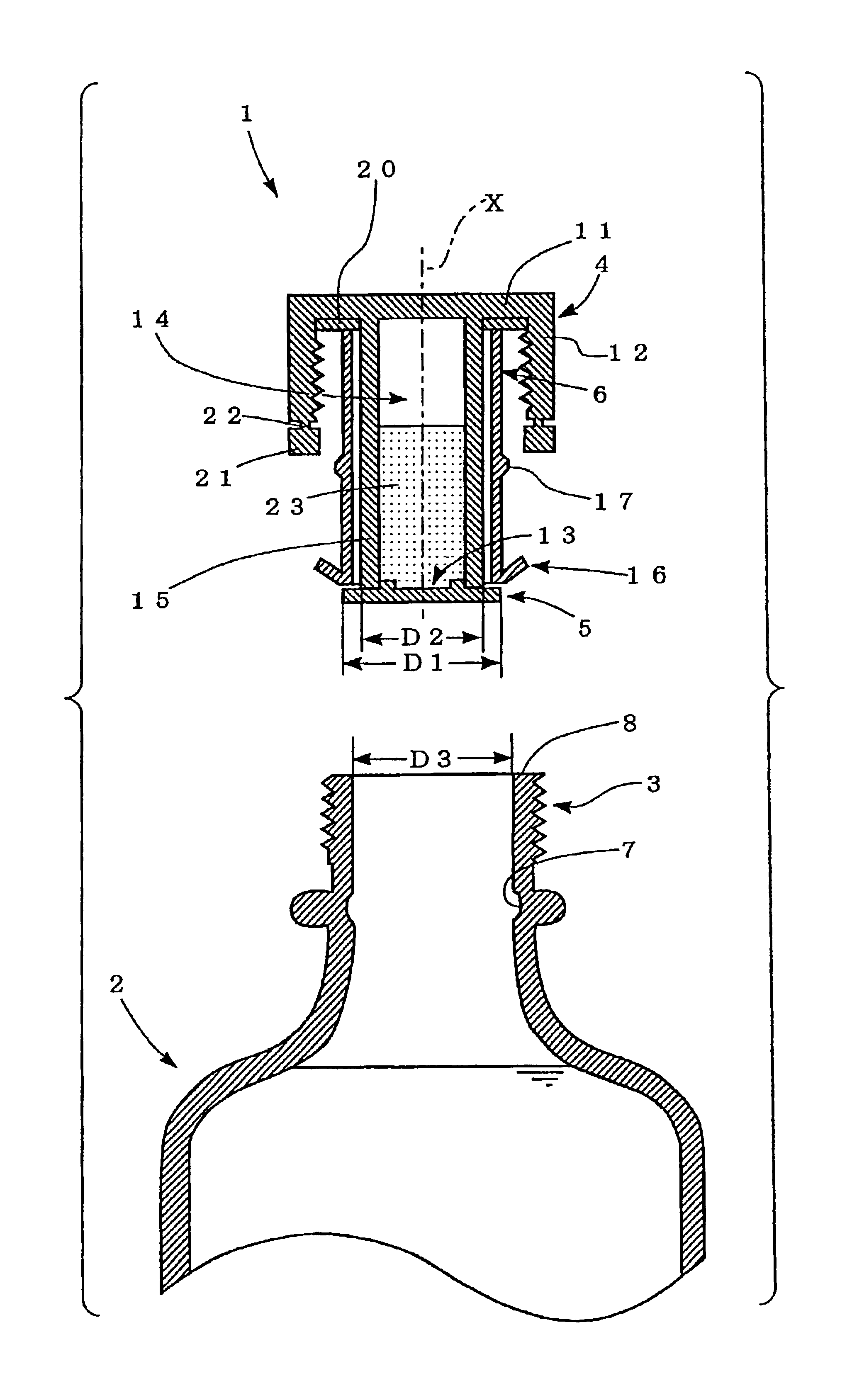
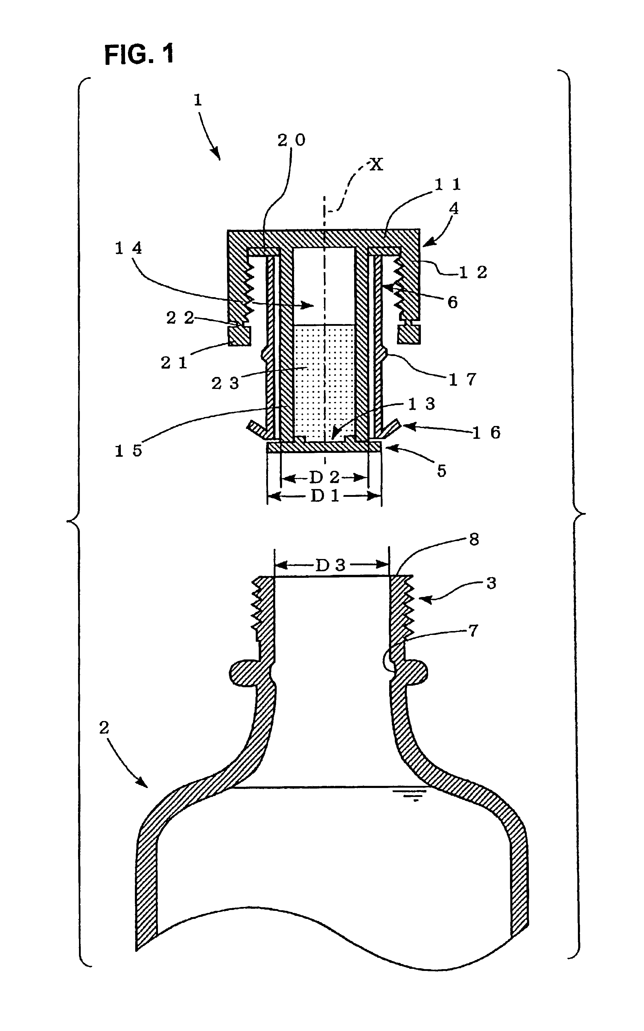
[0042]In FIGS. 1 and 2, an embodiment of cap to be used in sealing mechanism for vessel in respect of the present invention is shown.

[0043]A cap 1 is to be used in a sealing mechanism for a vessel 2 and has a plug portion 4, a seal plug 5 and a sleeve 6.

[0044]The plug portion 4 has a top board 11 to cover an opening portion 3 of the vessel 2, a side wall 12 projecting from the top board 11 along axis X of the plug portion 4 which wall has an inner circumferential surface fits on an outer circumferential surface of the opening portion 3, and a cylindrical wall 15 forming a receiving chamber 14 having an opening mouth 13 at its under end face which wall projects from the top board 11 at inner side of the side wall 12. Further, on bottom side of the top board 11, a packing 20 is attached. Furthermore, to under edge of the side wall 12, a cut-ring 21 is connected.

[0045]The seal plug 5 is to be fixed on the cylindrical wall 15 to seal the opening mouth 13 and its outer diameter D1 is lar...


PUM


Abstract

A cap has a plug portion, a seal plug and a sleeve. At the plug portion a side and a cylindrical wall project from a top board. An inner circumferential surface of the side wall fits on an outer circumferential surface of an opening portion of a vessel and covers the opening portion with the top board. The cylindrical wall forms a receiving chamber having an opening mouth at its under end face. The seal plug seals the opening mouth. The sleeve is loosely fitted on the cylindrical wall and opens the opening mouth by separating the seal plug from the cylindrical wall at relative movement of the cap. A sepal portion on the outer circumference of the sleeve is larger than inner diameter of the opening portion at its outer diameter and has flexibility to pass the inner diameter bending so as to avoid backward moving.

Description

BACKGROUND OF THE INVENTION[0001]1. Technical Field of the Invention[0002]This invention relates to such a sealing mechanism for vessel that enables to preserve liquid consists of several raw materials, a refreshing drink for example, in single vessel isolating the consisting raw materials from each other in condition that they can be mixed when they are used, and relates to a cap to be used in the mechanism which cap having receiving chamber for raw material.[0003]2. Prior Art[0004]A medicine to be used mixing two agents, a refreshing drink produced by mixing raw material into liquid or the like occasionally changes in quality in case where they have not used or consumed long time after they were mixed, because the mixed agents reacts or the raw material mixed into the liquid is deteriorated by sunlight or oxygen in air. Therefore, as a way to preserve these liquid or the like used or consumed mixing several raw materials and so on in condition their original qualities are kept, a ...

Claims


Application Information

Patent Timeline
IPC IPC(8): B65D51/28B65D51/24
CPCB65D51/2878B65D51/28
Inventor TAKAHASHI, MASASHIYOSHIWARA, TETSUO
Owner MASASHI TAKAHASHI
Learn More