Programmable power supply

a power supply and programmable technology, applied in the field of power supplies, can solve the problems of insufficient power, large external power supply, and difficulty in providing the necessary power curve for rechargeable batteries, and achieve the effect of small form factor power supply, high efficiency of conversion and regulation, and high efficiency

Inactive Publication Date: 2005-07-26
COMARCO WIRELESS TECH
View PDF73 Cites 41 Cited by
  • Summary
  • Abstract
  • Description
  • Claims
  • Application Information

AI Technical Summary

Benefits of technology

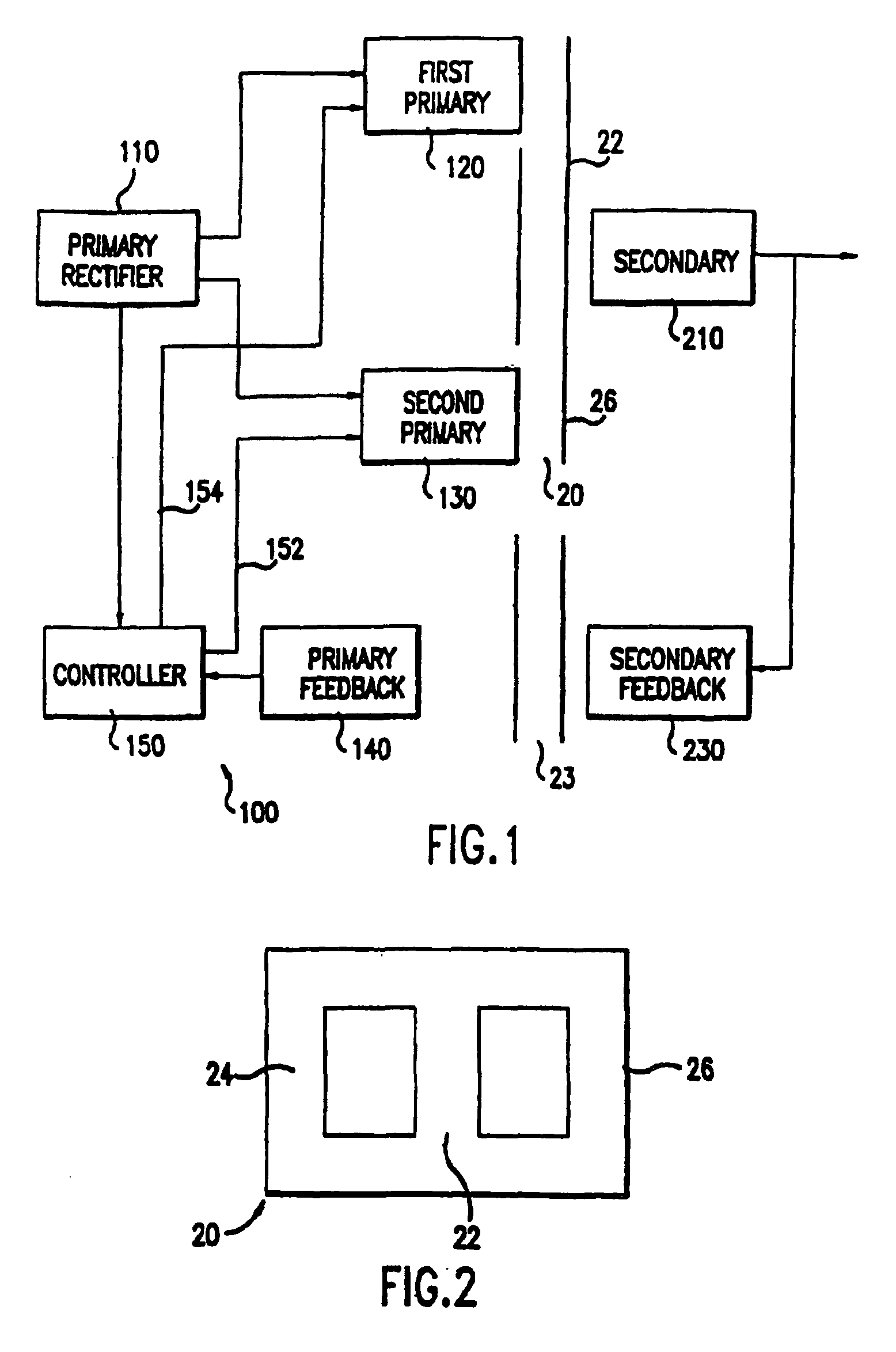
[0014]The controller provides a separate square wave signal to each of the two primary circuits and the phase of the square wave signals may be altered relative to each other as determined by the controller. The secondary circuit is positioned on the core relative to the two primary circuits so that the secondary circuit coil is positioned at a summing point on the core of the first and second primary circuit coils. The DC voltage and current levels produced at the output of the secondary circuit are monitored by the secondary feedback circuit to provide, through a secondary feedback coil and a primary feedback coil, a signal to the controller. The controller alters the phase between the signals driving the two coils to produce the desired output DC voltage and current at the secondary coils. This results in providing a regulated DC power supply with high efficiency.
[0015]By mounting all of the components on a printed circuit board using planar or low profile cores and surface mounted integrated circuits, a small form factor power supply can be attained. Given the high efficiency of the conversion and regulation, the system minimizes dissipation of heat permitting the entire power supply to be mounted within a high impact plastic container dimensioned, for example, as a right parallelepiped of approximately 2.85×5.0×0.436 inches, thereby providing a power supply that can readily be carried in a shirt pocket. It should be understood that changes in the overall dimensions may be made without departing from the spirit and scope of the present invention. Making a relatively thin package having relatively large top and bottom surface areas relative to the thickness of the package provides adequate heat dissipation.
[0016]Particular embodiments of the present invention utilize an improved transformer core that, by moving the relative position of the transformer legs, maximizes a ratio of the cross-sectional area of the transformer legs to the windings, thereby requiring less windings for the same magnetic coupling. Fewer windings means less area of a layer of a circuit board may be used so that the number of layers on the circuit board may be minimized. The improved transformer core also provides this maximized ratio while maintaining the ratio of the secondary and primary windings at a constant value. In alternative embodiments, different transformer topologies may be used.
[0017]It is an object of an additional embodiment of the present invention to alleviate the need for having a separate power supply for providing power for using each portable electronic device having distinct power requirements.

Problems solved by technology

Smaller power supplies do exist but frequently they lack sufficient power to charge new batteries such as nickel hydride batteries.
Further, the external power supply is bulky and may not be readily carried in typical cases for such notebook and sub-notebook computers.
In addition, conventional power supplies often have difficulty providing the necessary power curve to recharge batteries that have been thoroughly discharged.
While it has long been known to be desirable to reduce the size and weight of the power supply, this has not been readily accomplished.
Many of the components such as the transformer core are bulky and have significant weight.
Further, such power supplies may need to be able to provide DC power of up to seventy-five watts, thereby generating substantial heat.
Due to the inherent inefficiencies of power supplies, this results in substantial heat being generated within the power supply.
Reduction of the volume, weight and heat are all critical considerations for a power supply in this type of application and cannot be readily accomplished.
Therefore, users need multiple power supplies, which consumes space and increases unnecessary weight.
Typically, cellular telephone battery chargers have been bulky and are not readily transportable.
Moreover, cellular telephone battery chargers often take several hours, or more, to charge a cellular telephone battery.

Method used


Image

  • Programmable power supply
  • Programmable power supply
  • Programmable power supply

Examples


Embodiment Construction

[0065]As shown in the drawings for purposes of illustration, embodiments of the present invention are directed to an improved small form factor power supply. In preferred embodiments of the present invention, the small form factor power supply is packaged in a small volume and produces over 75 watts of power with temperatures below 140° F. Preferred embodiments are used to power portable computers. However, it will be recognized that further embodiments of the invention may be used with other electronic devices, such as computer peripherals, audio and video electronics, portable telephone equipment and the like.

[0066]Other embodiments of the present invention are more generally directed to a power supply which is capable of providing power to any selected one of a number of electronic devices in response to a programming signal. Each of the electronic devices is adapted for receiving input power at either a set operational voltage or a set operational current. The programming signal...


PUM


Abstract

A progammable power supply for providing a regulated DC output power is disclosed. The power supply provides the output power to any one of a plurality of electronic devices adapted for receiving the output power at an operational voltage or an operational current. The power supply receives a programming signal to maintain the output power at the operational voltage or operational current associated with a particular selected electronic device. Accordingly, by varying the programming signal, the power supply can be programmed to provide output power to any one of several electronic devices having differing input power requirements.

Description

RELATED APPLICATIONS[0001]This application is a continuation application of utility application Ser. No. 10 / 313,793, filed Dec. 5, 2002, now U.S. Pat. No. 6,809,943, which is continuation application of utility application Ser. No. 10 / 140,513, filed May 7, 2002, now U.S. Pat. No. 6,693,413, which is a continuation application of utility application Ser. No. 09 / 694,972, filed Oct. 24, 2000, now abandoned, which is a continuation-in-part application of utility application Ser. No. 09 / 310,461, filed May 12, 1999, now U.S. Pat. No. 6,172,884, which is a continuation-in-part application of utility application Ser. No. 09 / 213,018, filed Dec. 16, 1998, now U.S. Pat. No. 5,949,213, which is a continuation-in-part application of utility application Ser. No. 09 / 148,811, filed Sep. 4, 1998, now U.S. Pat. No. 6,091,611, which is a continuation application of utility application Ser. No. 08 / 994,905, filed Dec. 19, 1997, now U.S. Pat. No. 5,838,554, which is a continuation-in-part of utility appl...

Claims


Application Information

Patent Timeline
Patent Type & Authority Patents(United States)
IPC IPC(8): H02M3/337H02J7/00H02J7/02H02M3/28H02M1/00H02M3/00H02M3/338H01R13/66H02M3/24H05K1/16H01R13/24H01R13/22G06F1/26H02M1/42
CPCG06F1/26H01R13/6675H02J7/0008H02J7/0068H02J7/022H02M1/4258H02M3/00H02M3/156H02M3/28H02M3/33507H02M3/33523H02M3/3372H02M3/3378H02M3/3382H02M3/3387H02M7/003H05K1/165Y02B40/90H01R13/24H01R2201/16H01R2201/24H05K1/0203H05K1/0262H05K1/029H05K1/16H05K2201/086H05K2201/09063Y02B70/126H01F2027/2819H02J7/00041H02J7/02H02J2207/20H02J7/00047Y02B40/00Y02B70/10H02M3/003
Inventor LANNI, THOMAS W.
Owner COMARCO WIRELESS TECH
Why Eureka
Try Eureka