
Device for sintering a shaped body

a mold body and sintering technology, applied in the direction of glass shaping apparatus, lighting and heating apparatus, furnace components, etc., can solve the problem that the mold body cannot be contaminated by sealing oil evaporation during sintering, so as to prevent any oscillation of the link chain and limit the movement of the vertical hoisting

Inactive Publication Date: 2005-08-02
HERAEUS QUARZGLAS
View PDF11 Cites 0 Cited by
  • Summary
  • Abstract
  • Description
  • Claims
  • Application Information

AI Technical Summary

Benefits of technology

[0009]With this background, the present invention is based on the task to provide for a device of the above described type with a hoisting device in the interior of the chamber operated by a drive arranged outside of the chamber in such a way that the availability of the device and the quality of the mold body manufactured in the sintering process are improved, and that above all contaminations caused by leakages at the duct are to be excluded as far as possible. At the same time, the amount of maintenance required is to be reduced.

Problems solved by technology

Besides, a section of the drive shaft contaminated with seal oil cannot reach the inner space of the chamber so that the mold body cannot be contaminated by evaporating seal oil during sintering.

Method used


Image

  • Device for sintering a shaped body
  • Device for sintering a shaped body
  • Device for sintering a shaped body

Examples


Embodiment Construction

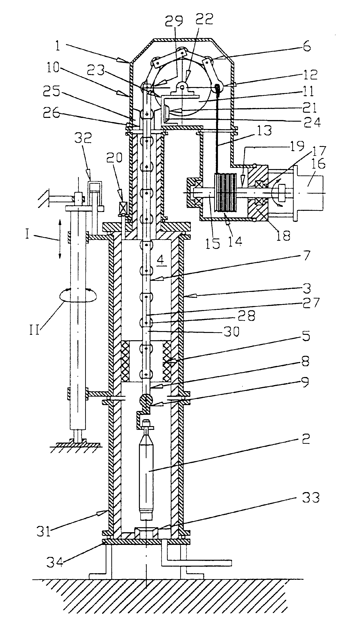
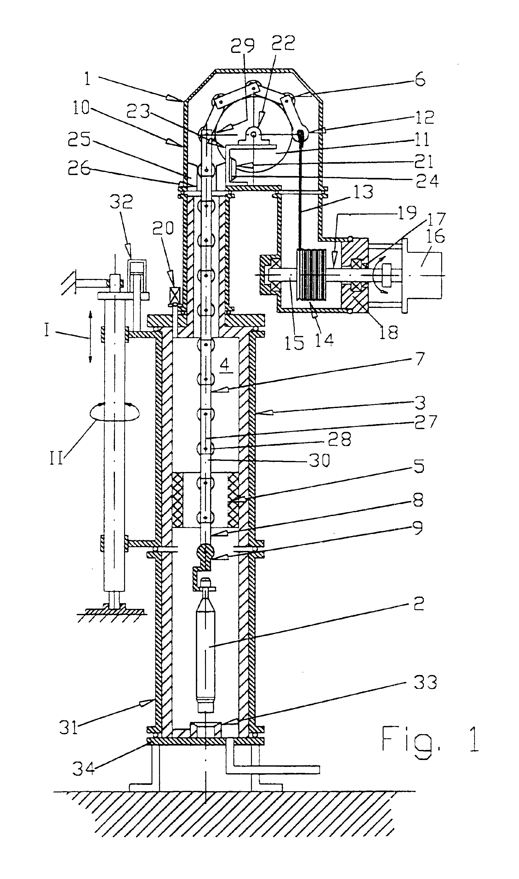
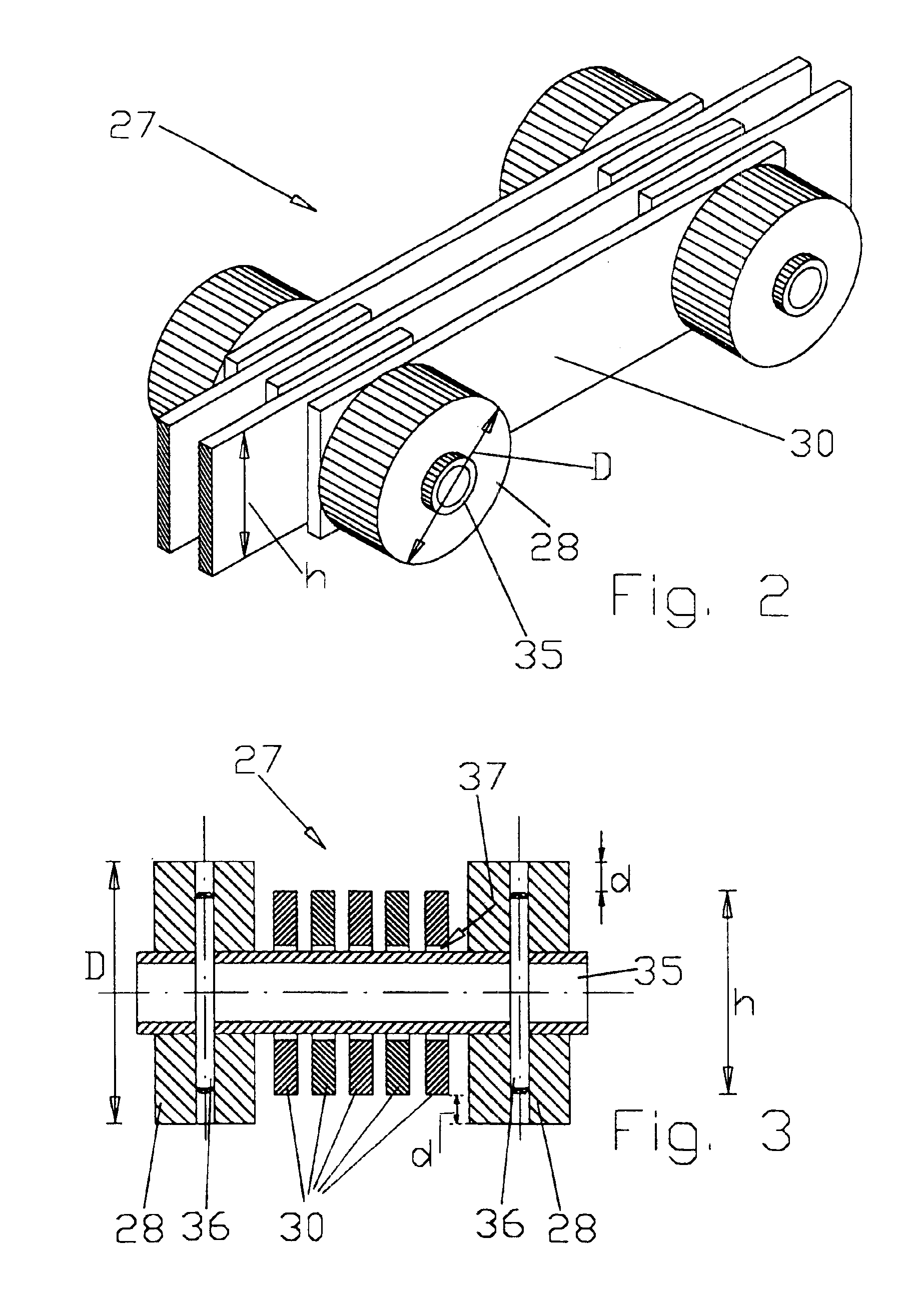
[0037]FIG. 1 shows in lateral sectional view a device 1 according to the invention for sintering of a porous mold body 2. As an elementary component, device 1 contains a gas-tight chamber 3, in the inner space 4 of which chamber 3 the mold body 2 can be continually fed vertically to a heating zone 5. This is effected by means of a hoisting appliance 6 with a link chain 7, the bottom end 8 of the latter having a rest 9 for the mold body 2. In the area of the upper boiler 10 of the chamber 3, the direction of the link chain 7 is reversed by means of a deviation wheel 11, the free end 12 of the link chain 7 opposite the mold body 2 being equipped with a traction rope 13. This traction rope 13 can easily be taken up on a winding appliance in the form of a take-up reel 14, thus allowing for the desired lifting movement of the mold body 2. The take-up reel 14 is flanged to a drive shaft 15 which is directly connected to a drive 116 arranged outside of the chamber 3. To seal the drive shaf...


PUM

PropertyMeasurementUnit
Temperatureaaaaaaaaaa
Forceaaaaaaaaaa
Diameteraaaaaaaaaa

Abstract

The invention concerns a device (1) for sintering of a porous mold body (2) in a gas-tight chamber (3), with the mold body (2) hanging loose from a link chain (7) so that it can be fed continuously to a heating zone (5). In the area of the upper boiler (10), the traction direction of the link chain (7) is reversed by a deviation wheel (11). The tensile force is transmitted via a traction rope (13) that can be taken up on a take-up reel (14), such take-up reel (14) being driven by a drive (16) arranged outside the chamber (3). A drive shaft (15) for the take-up reel (14) provides for easy sealing of the duct (18) towards the chamber (3), because only a rotation and not a simultaneous axial displacement is required for the hoisting movement, and moreover, because the duct (18) is arranged at a spatial distance from the heating zone (5). The link chain (7) consists of carbon fiber reinforced mineral carbon materials and is thus resistant to high temperatures, so that no contamination of the mold body (2) by released components of the material of the link chain (7) will occur.

Description

FIELD OF THE INVENTION[0001]This invention concerns a device for sintering of a mold body, especially of silicon dioxide soot, in a gas-tight chamber, the device for vertical feeding of the mold body into a heating zone being equipped with a hoisting appliance extending into an inner space of the chamber through a duct, such hoisting appliance being mobile by means of a drive arranged outside of the chamberBACKGROUND OF THE INVENTION[0002]In the manufacture of pre-molds for optical fibers or for semiconductor engineering, intermediate products are frequently used, the silicon dioxide mold body being present as a so-called soot body. For sintering, the mold body is fed into the heating zone of a zone melting furnace in which the mold body is heated to its softening temperature; thus, the transition is initiated. Because of the high quality demands, above all with applications in communication and semiconductor engineering, sintering is done in a gas-tight chamber to reliably avoid an...

Claims


Application Information

Patent Timeline
IPC IPC(8): C03B19/00C03B19/14C03B37/014F27B21/00F27B9/00F27B9/14C03B8/04F27D3/00
CPCC03B19/1453C03B37/0146C03B37/01486F27B21/00F27B9/147
Inventor CHRISTIANSEN, UWE
Owner HERAEUS QUARZGLAS
Learn More