Flushing a multi-port valve manifold

a multi-port valve and manifold technology, applied in the direction of manufacturing tools, lapping machines, instruments, etc., can solve the problems of increasing the velocity of the flushing liquid flowing through the manifold, reducing and expulsion of additional gas pockets, so as to increase the velocity of the flushing liquid and reduce the pressure within the manifold

Inactive Publication Date: 2005-08-02
AIR LIQUIDE ELECTRONICS US LP
View PDF3 Cites 7 Cited by
  • Summary
  • Abstract
  • Description
  • Claims
  • Application Information

AI Technical Summary

Benefits of technology

[0012]In one embodiment of this invention, gas pockets are flushed from a manifold by a method comprising introducing a flushing liquid (e.g., ultra pure water) into the manifold through a manifold intake. Before, during or after the introduction of the flushing liquid, a vent on the manifold is opened to permit at least a portion of the gas pockets to escape through the vent. The flushing liquid, at least a portion of any initial contents (e.g., residual slurry from a previous sample) that may be present within the manifold at the start of the flush, and typically at least another portion of the gas pockets are discharged from the manifold through a manifold outlet. The manifold is then flooded with the flushing liquid such that the manifold is filled and remains filled with the flushing liquid while the flushing liquid continues to flow through it. Wit

Problems solved by technology

This results in an increase in the velocity of the flushing liquid flowing through the manifold and this, in turn, results in the expulsion of additional gas pockets.
The introduction or flow of the flushing liquid into the manifold is then discontinued (although the manifold remains filled with the f

Method used


Image

  • Flushing a multi-port valve manifold
  • Flushing a multi-port valve manifold
  • Flushing a multi-port valve manifold

Examples


Embodiment Construction

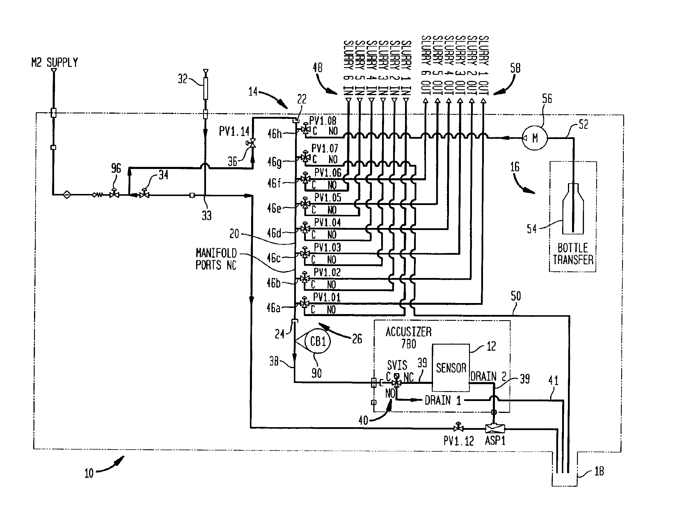
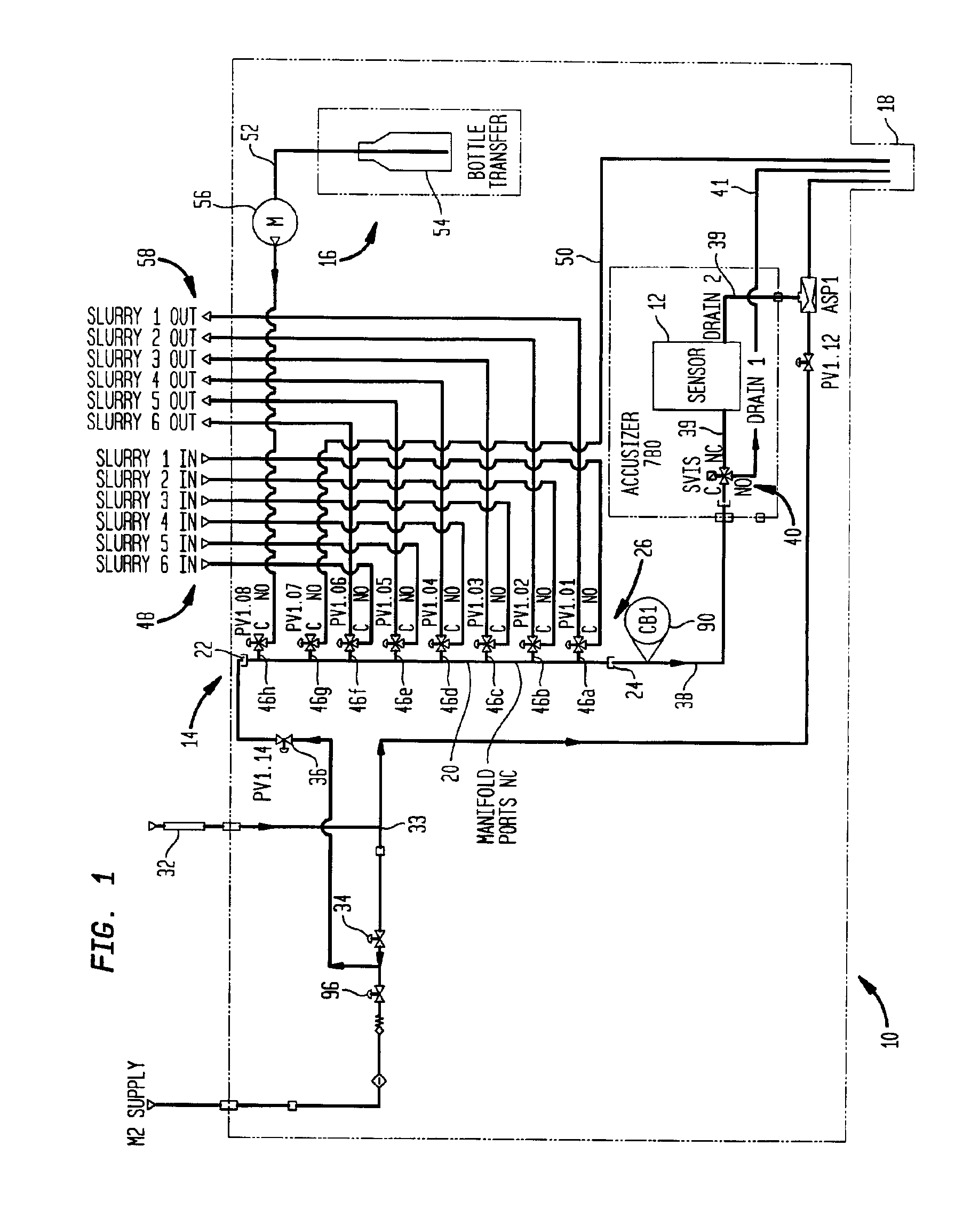
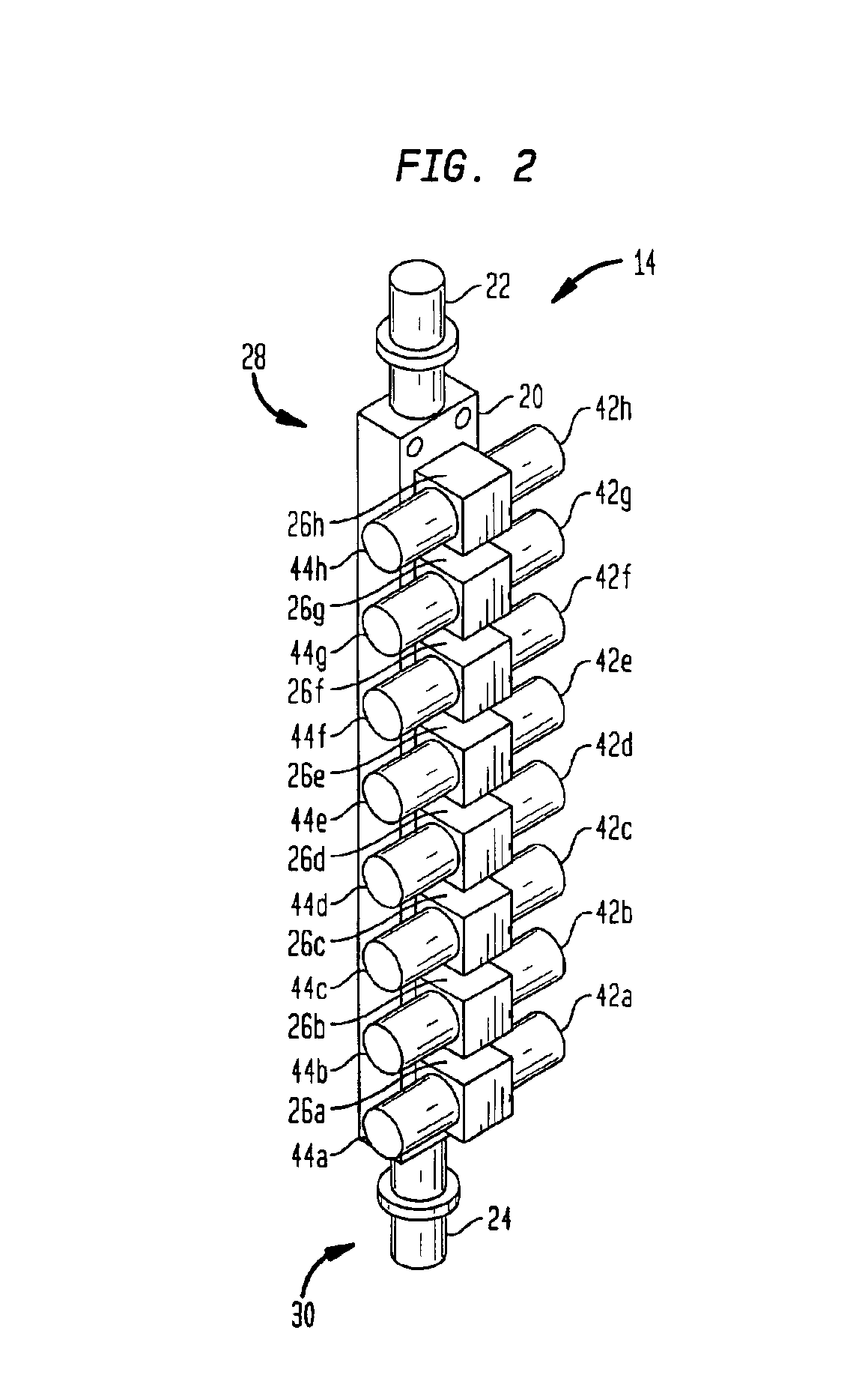
[0019]Various items of equipment, such as fittings, valves, mountings, pipes, sensors, monitoring equipment, wiring, and the like have been omitted to simplify the description. However, such conventional equipment and its uses are known to those skilled in the art and can be employed as desired. Moreover, although the invention is described below in the context of slurries used in chemical-mechanical polishing processes, those skilled in the art will recognize that the invention can be employed with, and has applicability to, many other and different processes.

[0020]Referring to FIG. 1, a schematic representation of a liquid sampling system 10 is illustrated. In preferred embodiments, system 10 comprises a liquid sampling system known as the intelligent Slurry Particle Equipment (iSPEQ) system. The iSPEQ system is operable to monitor the health of chemical-mechanical polishing slurries. An exemplary description of the iSPEQ system is provided in commonly-owned, co-pending U.S. paten...


PUM


Abstract

A method for flushing gas pockets from a manifold that forms a part of a liquid sampling system that is compatible with a chemical-mechanical polishing system is described. A flushing liquid, e.g., ultra pure water, is introduced into, and expelled from, the manifold to expel gas pockets from the manifold. The method comprises the steps of opening a manifold vent, filling the manifold with the flushing liquid, and closing the vent to increase the velocity of the flushing liquid flowing through the manifold. The introduction of the flushing liquid is discontinued, and thereafter, resumed. The discontinuation and resumption steps are preferably repeated The manifold is thus flushed of gas pockets.

Description

CROSS-REFERENCE TO RELATED APPLICATIONS[0001]Priority is claimed to U.S. provisional patent application Ser. No. 60 / 313,439 filed on Aug. 17, 2001.BACKGROUND OF THE INVENTION[0002]1. Field of the Invention[0003]The invention relates to flushing gas pockets from a manifold. In one aspect, the invention relates to flushing gas pockets from a manifold that forms a part of a liquid sampling system while in another aspect, the invention relates to flushing gas pockets from a multi-port valve manifold disposed within a liquid sampling system that includes a sensor for monitoring the health of a slurry used in a chemical-mechanical polishing system, the sensor sensitive to gas pockets.[0004]2. Description of the Related Art[0005]A chemical-mechanical polishing (CMP) system is often employed in the microelectronics industry to contour and / or polish semiconductor wafers. These systems typically contain and employ a “slurry” which is cycled throughout the system such that the slurry contacts ...

Claims


Application Information

Patent Timeline
IPC IPC(8): B08B9/00B24B37/04G01N1/00G01N15/02G01N15/00
CPCB08B9/00B24B37/04B24B57/02G01N35/1097G01N15/0205G01N2015/0011Y10T137/0424
Inventor CARLSON, STEPHEN JOHN
Owner AIR LIQUIDE ELECTRONICS US LP
Why Eureka
Try Eureka