Microfluidic device with ultraphobic surfaces

a microfluidic device and ultraphobic technology, applied in fluid dynamics, laboratory glassware, lighting and heating apparatus, etc., can solve the problems of limited fluid flow rate through the device, variability in pressure loss through microscopic flow channels, etc., to reduce the resistance to fluid flow, improve device efficiencies, and reduce the effect of intra-device pressur

Active Publication Date: 2005-08-02
ENTEGRIS INC
View PDF36 Cites 83 Cited by
  • Summary
  • Abstract
  • Description
  • Claims
  • Application Information

AI Technical Summary

Benefits of technology

[0010]It is anticipated that fluid flow channels in a microfluidic device having ultraphobic fluid contact surfaces will exhibit sharply reduced resistance to fluid flow, leading to greatly improved device efficiencies, lower intradevice pressures and improved fluid flow throughput. The ultraphobic surfaces will be durable, and capable of exhibiting predictable ultraphobic properties under fluid pressures up to the maximum design pressure.

Problems solved by technology

In turn, fluid flow rates through the device may be limited by the amount of pressure that can be tolerated by the device or the process that the device supports.
In addition, pressure losses through microscopic flow channels may vary greatly due to the characteristics of surfaces in the flow channel.

Method used


Image

  • Microfluidic device with ultraphobic surfaces
  • Microfluidic device with ultraphobic surfaces
  • Microfluidic device with ultraphobic surfaces

Examples


example 1

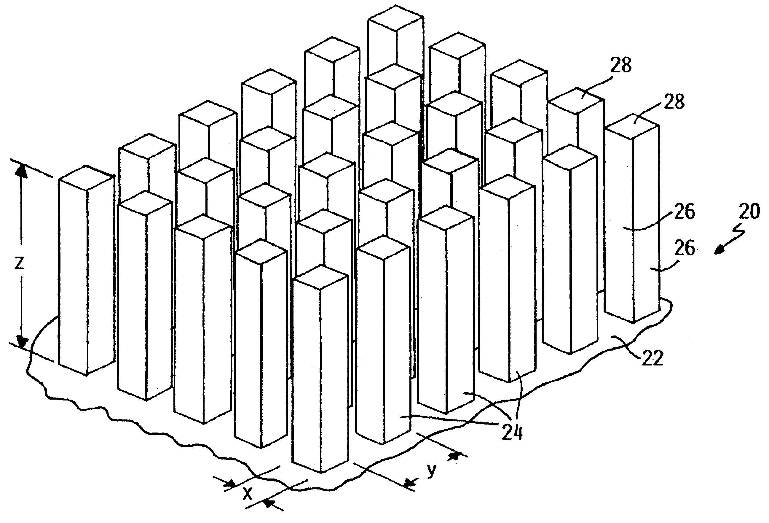
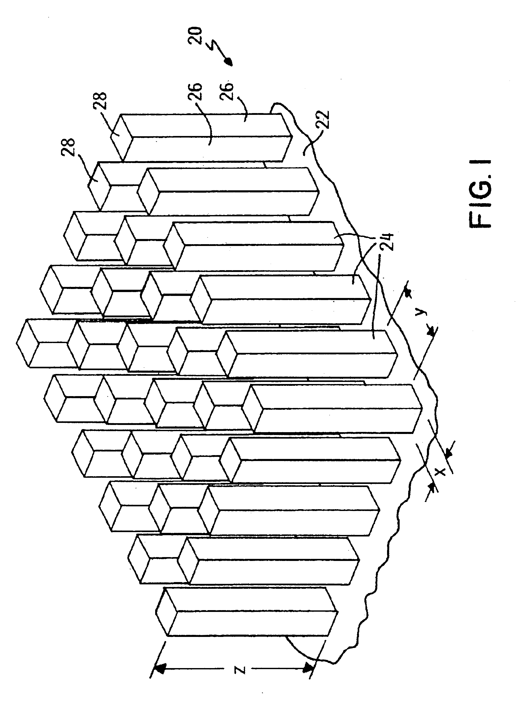
[0067]A cylindrical microscopic flow channel is to be formed in a silicon body to produce a microfluidic device. An ultraphobic surface is to be provided on the inwardly facing walls of the microscopic flow channel according to the present invention. The ultraphobic surface will consist of an array of square posts (ω=90°) disposed on the walls of the channel. The channel walls will also be coated with organosilane so that the channel has the following dimensions and characteristics:

R=1 μm

θa,0=110°

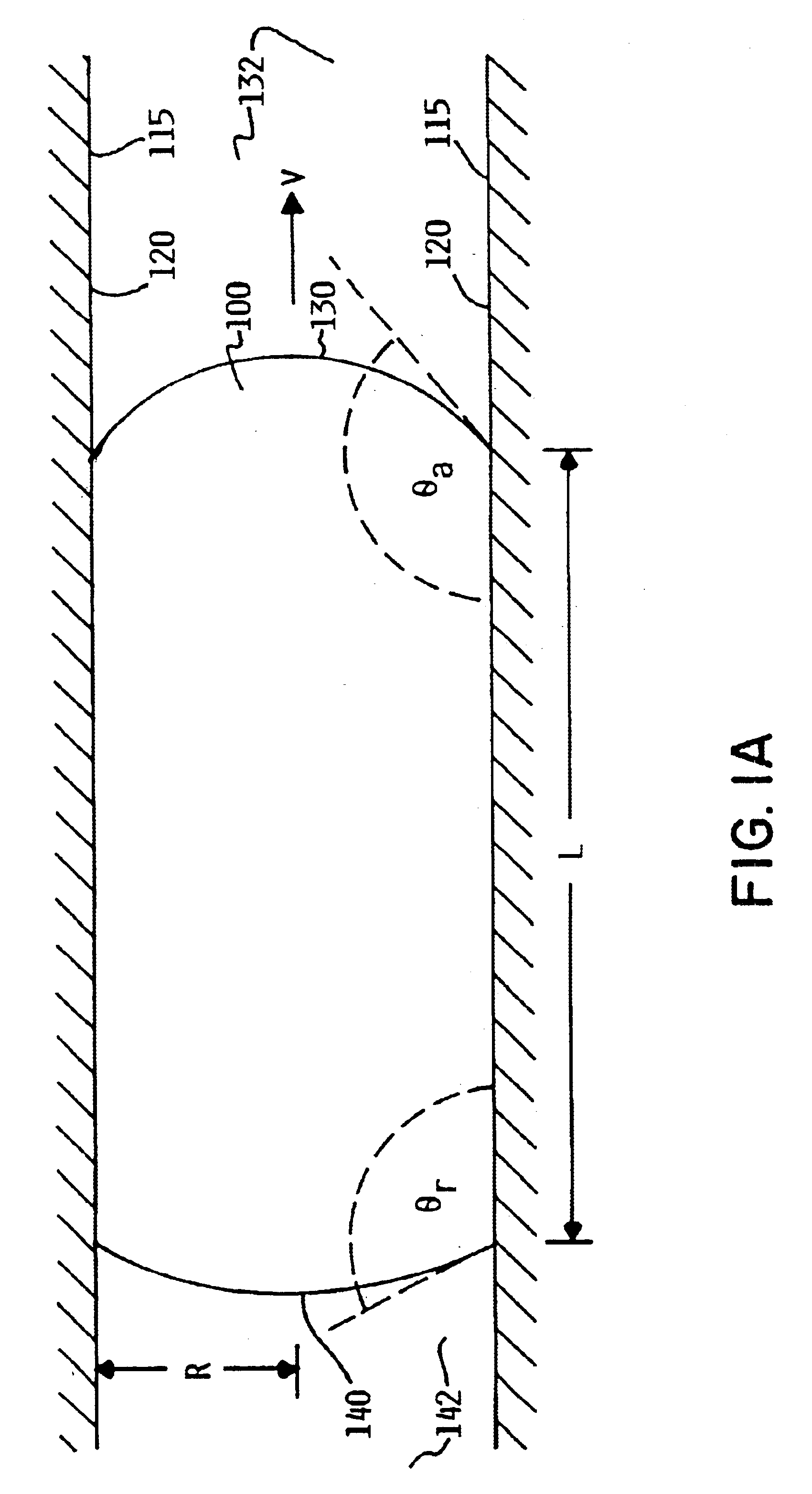
θr,0=90°[0068]A water slug in the flow channel has the following dimensions and characteristics:

γ=0.073 N / m

L=0.1 mm

v=0.1 mm / s[0069]If the flow channel has smooth fluid contact surfaces so that the actual advancing and receding contact angles of the slug (θa, θr) are substantially equal to the true advancing and receding contact angles for the fluid contact surface material, the pressure required to move the liquid slug through the smooth flow channel may be calculated as: Δ⁢ ⁢P=2⁢γ⁡(cos⁢ ⁢θ...

example 2

[0077]Assume a cylindrical microscopic flow channel in PFA plastic having the following dimensions and characteristics:

 R=10 μm

θa,0=110°

θr,0=90°[0078]Assume also a water slug in the flow channel:

γ=0.073 N / m

L=1 mm

v=0.1 mm / s[0079]Again, if the flow channel has smooth fluid contact surfaces so that the actual advancing and receding contact angles of the slug (θa, θr) are substantially equal to the true advancing and receding contact angles for the fluid contact surface material, the pressure required to move the liquid slug through the smooth flow channel may be calculated as: Δ⁢ ⁢P=2⁢γ⁡(cos⁢ ⁢θr-cos⁢ ⁢θa)R=2⁢(0.073)⁢(cos⁢ ⁢90-cos⁢ ⁢110)0.000010≈5×10³⁢Pa[0080]An array of square posts (ω=90°) is to be disposed on the fluid contact surface of the flow channel so as to form an ultraphobic surface.

 Selectx / y=λp=0.1[0081]So that:

θa1=λp(θa,0+ω)+(1−λp)θair=180°

and:

θr=λpθr,0+(1−λp)θair=171°[0082]The pressure for moving the liquid slug through the flow channel having ultraphobic fluid contact s...


PUM


Abstract

A microfluidic device having durable ultraphobic fluid contact surfaces in the fluid flow channels of the device. The ultraphobic surface generally includes a substrate portion with a multiplicity of projecting regularly shaped microscale or nanoscale asperities disposed in a regular array so that the surface has a predetermined contact line density equal to or greater than a critical contact line density, and so that the ratio of the cross-sectional dimension of the asperities to the spacing dimension of the asperities is less than or equal to 0.1.

Description

RELATED APPLICATIONS[0001]This application claims the benefit of U.S. Provisional Patent Application Ser. No. 60 / 462,963, entitled “Ultraphobic Surface for High Pressure Liquids”, filed Apr. 15, 2003, hereby fully incorporated herein by reference. This application U.S. patent application Ser. No. 10 / 454,742 entitled “Fluid Handling Component With Ultraphobic Surfaces”, filed Jun. 3, 2003, also hereby fully incorporated herein by reference.FIELD OF THE INVENTION[0002]This invention relates generally to microfluidic devices, and more specifically to a microfluidic device having ultraphobic fluid contact surfaces.BACKGROUND OF THE INVENTION[0003]There has been much recent interest and effort directed to developing and using microfluidic devices. Microfluidic devices have already found useful application in printing devices and in so-called “lab-on-a-chip” devices, wherein complex chemical and biochemical reactions are carried out in microfluidic devices. The very small volumes of liqui...

Claims


Application Information

Patent Timeline
Patent Type & Authority Patents(United States)
IPC IPC(8): B01L3/00B08B17/00B08B17/06B01L11/00B01L99/00
CPCB01L3/502746B08B17/06B08B17/065B01L9/52B01L2300/166Y10T428/24479B65G2201/0258B01L2400/086B01L13/02Y10T137/2224
Inventor EXTRAND, CHARLES W.WRIGHT, MICHAEL
Owner ENTEGRIS INC
Why Eureka
Try Eureka